Content last revised on October 18, 2026
Eye Diagram Voltage Margin and Differential Noise Floor Verification in High Vibration Bays
Pixel jitter and horizontal noise bands should be investigated at the complete display link rather than attributed to the panel alone. In a cabinet containing variable frequency drives or other high energy switching equipment, inspect the LVDS or TTL transmission path for shield termination quality, connector retention, cable routing, and separation from power switching conductors.
A shielded FFC or differential display cable should be bonded according to the host equipment grounding architecture. The objective is to control common mode current without creating an unintended circulating path through the panel frame. Ferrite components may be considered only after the signal spectrum and common mode behavior have been measured, because an unsuitable component can alter edge shape and reduce receiver margin.
Use an oscilloscope with suitable differential probing at the transmitter and receiver ends. Compare clock stability, data eye opening, edge symmetry, and channel to channel behavior while the equipment changes operating state. TTL and LVDS are not interchangeable interfaces; the controller documentation must define the signaling standard, pin assignment, voltage domain, and timing relationship. A clean source waveform does not prove that the panel receives valid data after cable loading and connector transitions.
Clock jitter and data hold time should be evaluated across the actual enclosure temperature range. If the eye closes only when a drive, relay, or contactor operates, inspect grounding and cable coupling before changing panel settings. The engineering target is a stable receiver margin at the panel connector, verified under the same vibration and switching conditions expected in service.
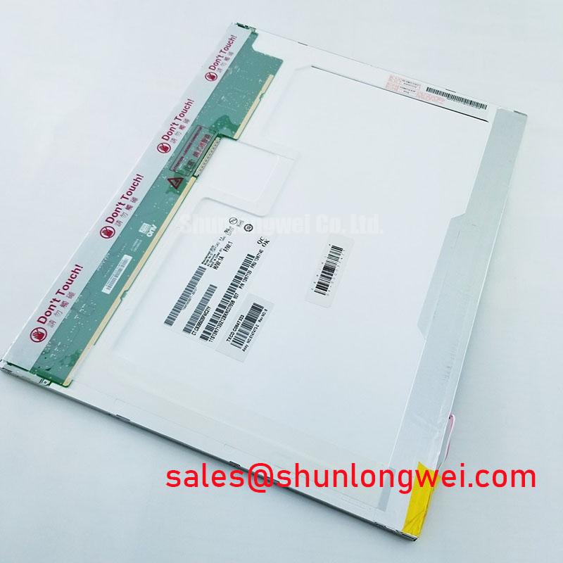
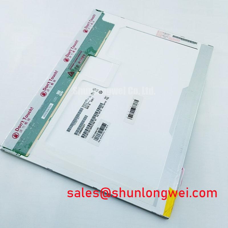
When the B150XG02 V1 is considered for a railway passenger information display or cab signalling terminal, the integrator should validate the complete harness, controller, and enclosure grounding arrangement as one signal path. The panel itself should not be presented as independently certified for railway EMC performance.
Polarizer Durability and Optical Retardation Film Inspection under Direct Industrial Lighting
Inspect the active viewing area with full screen white, black, red, green, blue, and mid gray images. This sequence helps separate visible pixel defects from cable faults, timing problems, contamination, and nonuniform backlight behavior. Record the position of any persistent bright or dark point and repeat the observation after the panel reaches a stable operating condition.
The supplied baseline classifies the unit as a TFT LCD active matrix color display module, but it does not establish a confirmed TN, IPS, or MVA optical mode. Viewing cone, grayscale inversion behavior, retardation film construction, surface treatment, contrast, and chromaticity therefore require confirmation from the panel documentation used by the original system. Do not apply a viewing angle figure from another AUO family to this model.
Under direct industrial lighting, inspect reflections while displaying dark text on a light background. Surface glare can reduce character contrast even when the panel is electrically healthy. A bezel, cover glass, or optical bonding layer can also change reflections and apparent black level. If an optical bonding conversion is being considered, the integrator should evaluate adhesive compatibility, sealing, serviceability, thermal expansion, and optical uniformity with the complete enclosure.
For a practical selection review, compare the confirmed panel identity with the host requirements before approving a substitute or redesign.
| Evaluation item | B150XG02 V1 baseline | System verification point |
|---|---|---|
| Manufacturer | AUO | Match the original equipment record |
| Product category | Industrial grade LCD/HMI panel | Confirm controller and mechanical compatibility |
| Display construction | TFT LCD active matrix color display module | Confirm optical mode and image timing |
| Form factor status | Not defined by the supplied baseline | Check mounting, bezel, connector, and cable clearance |
| Electrical interface | Not defined by the supplied baseline | Use the original panel documentation for pinout and supply requirements |
Industry display practices and optical evaluation methods can be compared with information published through the Sharp Display Solutions Official Portal. That reference should support general display evaluation only and should not be treated as an AUO specification for this model.
High Voltage Striking Potential and Secondary Coil Insulation Testing
Do not apply a CCFL ignition test or an LED driver test to the B150XG02 V1 until the installed backlight architecture has been identified from the original equipment records. A high voltage cold cathode circuit and a constant current LED circuit require different instruments, safety controls, connector handling procedures, and fault interpretations.
If the assembly uses a high voltage backlight system, insulation testing belongs to the complete approved backlight and harness design. Keep the panel disconnected from sensitive controller electronics during any test defined by the equipment manufacturer, and use the specified test method rather than selecting a withstand value from a different display family. Leakage, arcing, acoustic noise, or an intermittent start condition can originate in the harness, inverter, connector, or mounting environment.
If the assembly uses an LED driver, inspect current regulation, enable sequencing, dimming behavior, and thermal distribution at the backlight connector. PWM frequency and duty cycle are system parameters, not confirmed B150XG02 V1 factory specifications. The controller designer should verify that the selected driver produces stable visual output without visible flicker, audible interaction, or excessive localized heating.
Differential data routing also deserves attention in high EMI cabinets. Controlled impedance and pair skew should be established by the controller and harness design, then checked against the receiver requirements. A generic cable value cannot guarantee correct operation because connector geometry, trace length, dielectric construction, and termination behavior all influence the waveform.
💡 Bench Tip: Disconnect power before inserting or removing the display cable, keep the connector parallel during engagement, and use an ESD wrist strap when handling the exposed panel interface.
Thermal Cycling Degradation of Polarizer Adhesives and Sealant Gasket Integrity
Thermal evaluation should begin with a visual inspection of the polarizer edge, bezel contact area, sealing surfaces, and cable exit after controlled temperature exposure. Look for lifting, bubbles, edge whitening, frame interference, moisture marks, or changes in localized brightness. These observations are useful screening indicators, but they do not by themselves establish a service life prediction.
At low temperature, liquid crystal response can become visibly slower and gray transitions may appear less uniform. At elevated temperature, black level, brightness distribution, and mechanical alignment can shift with the enclosure and mounting stress. The relevant acceptance limits must come from the host equipment specification and the confirmed panel documentation.
Perimeter sealing should be evaluated together with the front cover, rear enclosure, cable entry, and pressure equalization strategy. A panel cannot independently guarantee an enclosure’s dust or moisture protection. If optical bonding or a protective window is added, designers should check adhesive expansion, compression points, trapped air, condensation risk, and service replacement procedures across the intended thermal cycle.
Backlight uniformity should be measured at several screen positions rather than judged from the center alone. A local hot area may result from driver placement, restricted airflow, cover pressure, or an uneven thermal interface. Improve heat spreading and avoid concentrated mechanical loading only after measurements identify the dominant condition.
For HMI consoles, CNC operator pendants, railway passenger information terminals, or cab display assemblies, the B150XG02 V1 should be accepted only after its optical, electrical, mechanical, and environmental interfaces have been matched to the host design. The engineering reference The Ultimate Guide to Industrial TFT LCD Technology provides additional context for display selection, signal integrity, and integration constraints.