The Ultimate Guide to Industrial TFT LCD Technology: Principles, Selection, and Common Myths
For embedded engineers, sourcing managers, and product designers in the industrial sector, the display module is often the single most critical interface between machine and operator. It is the face of the product. Yet, it remains one of the most technically misunderstood components in the Bill of Materials (BOM).
A common scenario in prototype development involves a machine that functions perfectly on the workbench. However, when the device is installed in its final environment—such as a medical cart viewed from above, or a CNC controller mounted at waist height—the display becomes unreadable. Colors wash out, blacks turn to grey, and the interface becomes a safety hazard. This is not necessarily a manufacturing defect; it is often a fundamental misunderstanding of the underlying physics of Liquid Crystal Displays (LCDs).
To select the correct display for harsh environments, heavy machinery, or precision instrumentation, engineers must look beyond basic datasheet parameters like resolution and brightness. This guide serves as a technical pillar to understand the “Active Matrix” architecture. We will deconstruct how Thin Film Transistors (TFTs) control light, analyze the microscopic structure of pixels, and provide a definitive engineering explanation for the notorious “Grayscale Inversion” phenomenon.
1. What is Active Matrix TFT Technology?
To appreciate modern industrial displays, one must understand the evolution from Passive Matrix to Active Matrix. In early “Passive Matrix” Liquid Crystal Displays (PMLCD), pixels were addressed by a simple grid of intersecting wires. As resolution increased, this method failed because the liquid crystals responded too slowly to rapid voltage changes, resulting in “crosstalk” (ghosting) and poor contrast.
The industry solution was the integration of the Thin Film Transistor (TFT), ushering in the era of Active Matrix LCDs (AMLCD). Unlike its passive predecessor, an Active Matrix screen is not just a grid; it is a complex semiconductor device where every single pixel is driven by its own dedicated circuit.
The Role of the Transistor and Capacitor
In a TFT LCD, every sub-pixel on the glass substrate contains a microscopic transistor and a storage capacitor (Cst). You can conceptualize the TFT as a high-speed electronic gate valve.
- The Switch (TFT): When the gate line (row) is activated, the TFT turns “ON,” allowing the source voltage (video data) to charge the pixel electrode.
- The Hold (Capacitor): This is the critical differentiator. Once the voltage is charged, the TFT turns “OFF.” The integrated capacitor holds this electrical potential until the next refresh cycle (typically 16.6ms for a 60Hz display).
This “Sample and Hold” architecture isolates the pixel from interference. It ensures that a pixel changing color at the top of the screen does not affect the voltage of a pixel at the bottom. For a deeper understanding of the semiconductor physics behind these switches, you can refer to the Wikipedia entry on Thin-film transistors, which details the evolution from Amorphous Silicon (a-Si) to modern Oxide semiconductors.
For applications requiring extreme visual stability, such as all-weather digital signage, this active control is non-negotiable to prevent flickering and signal decay.
Pixels and Sub-pixels: RGB vs. RGBW Architecture
If you examine a standard industrial TFT panel under a microscope, you will not see a single block of color. Instead, you will see a mosaic of tiny rectangles called sub-pixels. A single “Pixel” is traditionally composed of three sub-pixels: Red, Green, and Blue (RGB).
However, industrial requirements for sunlight readability have driven the adoption of RGBW (Red, Green, Blue, White) technology. Standard color filters absorb a significant percentage of the light generated by the Backlight Unit (BLU). By adding a transparent (White) sub-pixel, the display allows a portion of the pure backlight spectrum to pass through unfiltered.
This technique can increase the effective luminance by up to 50% without increasing the power consumption of the LED backlight—a critical engineering trade-off for battery-powered handheld terminals or HMIs used in bright outdoor ambient light.
2. Deep Dive: Inside the TFT Internal Structure
To understand failure modes, thermal limits, and durability, engineers must visualize the LCD module as a precision-engineered optical “sandwich.” An industrial TFT LCD is a stacked assembly of optical, chemical, and electrical layers.
The Circuit Geometry (The TFT Backplane)
The active circuitry is deposited on the rear glass substrate. This circuit matrix involves two primary orthogonal signal lines:
- Gate Lines (Scan Lines): Running horizontally, these control the ON/OFF state of the transistor gates.
- Source Lines (Data Lines): Running vertically, these carry the analog voltage signal that determines the brightness of the sub-pixel.
The intersection of a Gate Line and a Source Line defines a pixel address. However, they are electrically isolated by an insulating layer to prevent short circuits. The precision of this layering is what defines the yield rate of the panel manufacturer.
The Optical Stack and Polarization
Liquid crystals do not emit light; they modulate it. The light path travels as follows:
- Backlight Unit (BLU): Usually an array of LEDs generating white light.
- Bottom Polarizer: This film filters the light, ensuring it vibrates in only one specific plane.
- Liquid Crystal Layer: This is the active element. Depending on the voltage applied, the liquid crystal molecules rotate, twisting the polarization of the light passing through them.
- Color Filter (CF) Glass: Contains the RGB pigment matrix.
- Top Polarizer: Oriented 90 degrees relative to the bottom polarizer (in a standard TN setup). If the liquid crystal has twisted the light correctly, it passes through; otherwise, it is blocked, creating a black pixel.
The physics of polarization is central to this process. For a rigorous explanation of how light waves are filtered, the Britannica entry on Polarization provides an excellent foundational overview.
In industrial environments, the chemical stability of these polarizers is vital. Standard consumer polarizers may bubble or delaminate under high heat (above 70°C) or high humidity. Industrial-grade modules use “Wide Temperature” polarizers with specialized iodine or dye-based chemistries. For maintenance teams, understanding these layers is crucial when defining protocols for safe cleaning and preventing chemical damage to the screen surface.
3. The Core Engineering Pain Point: Grayscale Inversion
One of the most persistent issues in industrial display integration is the phenomenon of “Grayscale Inversion.” This occurs when a display is viewed from a sharp angle, and the colors suddenly shift—black becomes white, and the image resembles a photographic negative.
Why Does Inversion Happen?
This artifact is inherent to Twisted Nematic (TN) technology, which remains the dominant choice for cost-sensitive industrial meters and instrumentation due to its low price and high transmission efficiency.
In a TN panel, the liquid crystal molecules are rod-shaped. They are anchored to the glass surfaces but tilt when voltage is applied. Because of this rod-like asymmetry, the light is blocked effectively when viewed from one angle (along the long axis of the molecule) but leaks through when viewed from the opposite angle. This leakage disrupts the intended brightness curve (Gamma curve), causing the darker shades to appear brighter than the lighter shades—hence, “inversion.”
Decoding the Datasheet: 6 o’clock vs. 12 o’clock
Engineers often confuse “Viewing Angle” with “Viewing Direction.” These are distinct parameters in a specification sheet.
- Viewing Angle (e.g., 70/70/60/70): This defines the cone within which the Contrast Ratio (CR) remains above 10. It indicates where the text is legible, not necessarily where the colors are correct.
- Gray Scale Inversion Direction (e.g., 6 o’clock): This is the most critical parameter for mechanical design. It specifies the angle at which the image will degrade the most.
The Golden Rule of Selection:
If a datasheet specifies a “6 o’clock” viewing direction, it means the display is optimized to be viewed from the 12 o’clock position (looking down). The inversion occurs at the 6 o’clock position (looking up from the bottom).
Practical Application:
If you are designing a dashboard for a forklift where the operator sits above the screen and looks down, a “12 o’clock” display (which inverts when viewed from above) would be a catastrophic choice. You must select a “6 o’clock” display. Conversely, for an overhead monitor in an aircraft, you need a “12 o’clock” display. Getting this wrong necessitates costly tooling changes.
4. Selection Decision: TN vs. IPS Technology Routes
When specifying a display, the decision usually boils down to TN (Twisted Nematic) versus IPS (In-Plane Switching). While marketing materials often laud IPS as universally “superior,” a Total Cost of Ownership (TCO) analysis reveals that TN still has a place in engineering. See our detailed breakdown on Industrial vs. Consumer Display TCO for a financial perspective.
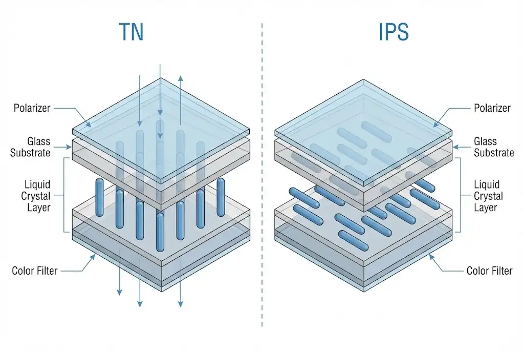
TN (Twisted Nematic) Technology
Mechanism: Liquid crystals twist 90 degrees vertically between the glass substrates.
- Engineering Pros:
- Cost Efficiency: Simplest manufacturing process with high yield.
- Response Time: Extremely fast (2ms – 5ms), preventing motion blur in rapidly changing data readouts.
- Power Efficiency: Higher light transmittance means lower backlight current is needed for the same brightness.
- Engineering Cons:
- Narrow viewing angles.
- Subject to Grayscale Inversion.
- Color depth is often limited to 6-bit (262k colors) rather than true 8-bit.
- Best Use Cases: Digital multimeters, gas pump displays, and fixed-position industrial controllers.
IPS (In-Plane Switching) Technology
Mechanism: The liquid crystals rotate parallel to the glass plane. This technology was developed specifically to address the viewing angle limitations of TN panels. For a historical and technical overview, Wikipedia’s article on IPS Panels covers the development from Hitachi to modern implementations.
- Engineering Pros:
- No Grayscale Inversion: Colors remain accurate from virtually any angle (typically 178°/178°).
- Pressure Stability: Touching the screen does not produce the “ripple” or “puddling” effect common in TN screens, making IPS ideal for touchscreens.
- Orientation Agnostic: Can be mounted in Portrait or Landscape mode without modifying the polarization layers.
- Engineering Cons:
- Higher manufacturing cost due to complex electrode structures.
- Lower transmittance (requires stronger backlights, generating more heat).
- Best Use Cases: Medical imaging diagnostics, marine navigation, Bar-type displays for public transport, and handheld devices.
Comparison Matrix for Engineers
| Feature | TN Panel (Industrial) | IPS Panel (Industrial) |
|---|---|---|
| Viewing Angle | Limited (e.g., 70°/70°/60°/70°) | Wide / Full (e.g., 85°/85°/85°/85°) |
| Grayscale Inversion | Present (Direction dependent) | Absent |
| Response Time | Fast (2ms – 5ms) | Moderate (20ms – 30ms) |
| Contrast Ratio | Typically 500:1 – 800:1 | Typically 800:1 – 1500:1 |
| Touchscreen Suitability | Fair (prone to puddling) | Excellent (Hard screen) |
Conclusion: Engineering for Reality
Selecting an industrial TFT LCD is a multi-dimensional optimization problem involving cost, power consumption, environmental durability, and optical performance. It is not merely about choosing the screen with the highest resolution; it is about matching the panel’s physics to the user’s ergonomic reality.
While IPS technology solves the viewing angle and inversion problems, TN technology remains a viable, power-efficient choice for stationary applications where the operator’s position is fixed. The most common engineering failure is not choosing the “cheap” screen, but choosing the wrong viewing direction for that screen.
Ready to select the right display for your next project?
Whether you need the robust sunlight readability of an RGBW panel or the wide viewing angles of an IPS module, understanding these fundamentals is the first step. For further reading on integrating these displays into space-constrained environments, explore our guide on Bar-Type LCDs for Constrained Spaces, or dive into the power electronics that drive these systems in our Power Semiconductor Selection Guide.
Content in This Series

Microscopic Analysis of TFT LCDs: Pixel Structure and Working Principles

Deep Dive: Grayscale Inversion and Why Your Industrial Display Loses Color Accuracy