

Content last revised on October 19, 2026
Preventing Localized Light Guide Plate (LGP) Compression Warp on Dark Screen Fields
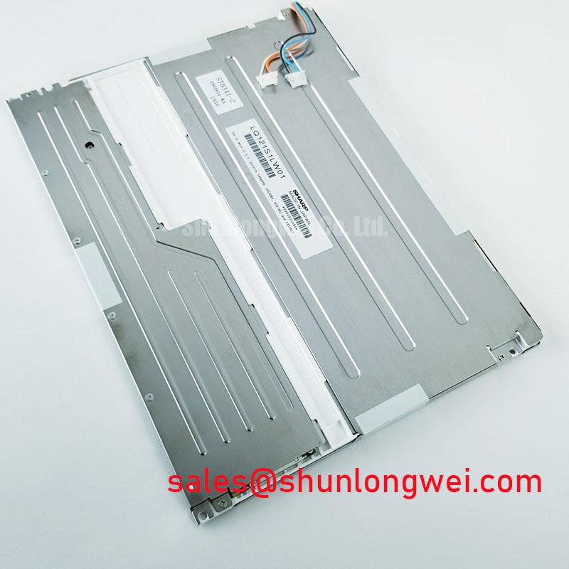
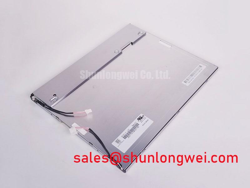
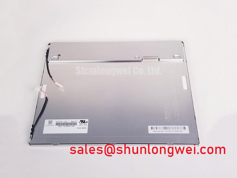
The G121I1-L01 is identified here as an AUO TFT-LCD active matrix color display module for industrial LCD/HMI integration. Replacement assessment should treat the panel, controller, backlight supply, cable assembly, and enclosure as an interacting display system. A matching outline alone does not establish electrical or optical compatibility.
| Product identification | Specification or integration checkpoint |
|---|---|
| Model | G121I1-L01 |
| Manufacturer | AUO |
| Product category | Industrial LCD/HMI panel |
| Module construction | TFT-LCD active matrix color display module |
| Electrical, optical, and mechanical limits | Consult Datasheet for resolution, outline dimensions, supply voltage, interface, timing, backlight requirements, mounting limits, and operating temperatures. |
- Disconnect power and compare the G121I1-L01 label, connector orientation, and cable routing with the display removed from the equipment.
- Inspect bezel contact, gasket seating, and mounting supports for uneven pressure before tightening the display assembly.
- Check connector locks and flexible cable folds for incomplete engagement, abrasion, or strain transferred from the enclosure.
- Record whether the fault appears during startup, after temperature changes, or only when nearby equipment operates.
Inspect a uniform dark image before and after fitting the bezel, keeping brightness and viewing position unchanged. As a Design Consideration, a bright patch that changes with enclosure loading warrants inspection of gasket compression, bracket alignment, and rear clearance. This comparison helps localize assembly pressure without assuming that the panel contains a particular light guide construction.
Support the module at its intended mounting features and keep the bezel from pressing on the active display area. Gaskets should seat continuously without folds, displaced corners, or trapped cable sections. Where the enclosure procedure specifies a crosswise tightening sequence, apply it progressively using the approved fastener torque. Thread engagement, bracket stiffness, and mounting geometry determine the permissible load; a generic screw torque should not become a G121I1-L01 specification.
For sunlight evaluation, compare readable text and dark backgrounds through the actual protective window under the expected illumination and viewing direction. Surface reflections can reduce apparent contrast even when the displayed image remains electrically correct. The general viewing angle characteristics of LCDs explain why observation position matters; they do not establish this panel’s contrast or surface treatment.
When comparing the TCG121WXLRFVNN-AN40, check its documented dimensions, resolution, connector arrangement, and optical characteristics independently. Its role here is a comparison candidate, with interchangeability dependent on those checks. Evaluation for an AGV or forklift telematics display should also cover enclosure vibration, cable restraint, and readability through the installed window.
Radiated Emissions Compliance (CISPR Class A/B) via Backplate Multi-Point Star Grounding
Correlate pixel jitter or horizontal noise bands with machine operating states before changing the display cable or grounding arrangement. As a Design Consideration, inspect shield continuity, connector shell contact, and chassis bonding against the equipment schematic. Backplate grounding is one part of the enclosure design; neither multiple bonds nor a star arrangement independently establishes CISPR compliance.
Where the cable assembly provides a shield termination, preserve its intended contact geometry and avoid routing signal cables alongside switching power conductors. Selective common-mode suppression can be evaluated during interference testing, with placement and impedance chosen from measured noise behavior. Such measures belong to the system integration assessment and are not established accessories or requirements of the G121I1-L01.
At the controller interface, compare the actual transmitter and receiver specifications for clock timing, data mapping, and setup and hold requirements. Inspect signal integrity at the receiving connection with suitable measurement equipment, including temperature conditions covered by the equipment specification. A stable image at room temperature does not establish timing margin throughout the approved operating range.
Flexible cables should follow the enclosure’s intended bend path without a sharp crease at the connector exit. Restrain the harness so vibration does not repeatedly flex the same section or pull against the latch. The Ultimate Guide to Industrial TFT-LCD Technology provides broader background for separating interface behavior from optical faults. Emissions compliance remains a measurement of the assembled equipment under the applicable test configuration.
Mitigating Gray-to-Gray (GTG) Response Time Escalation during Cold-Start Machine Power-Up
Compare moving text and changing gray patterns after a temperature soak and again after the display stabilizes. As a Design Consideration, reduced liquid crystal mobility at lower temperatures can slow optical transitions. Record ambient conditions and image behavior within the approved operating envelope rather than assigning an unsupported cold-start response time to this model.
Examine gasket contact and mounting freedom after temperature changes, because differential expansion can alter pressure around the display perimeter. Manage condensation through the equipment’s environmental procedure before applying power. Seal composition and thermal cycling capability require product-specific evidence; an industrial application label alone does not establish either characteristic.
Check the controller’s power sequence when startup produces a white screen or shutdown leaves a persistent image. Compare panel supply, valid image data, and backlight enable behavior with the specified sequence. For dimming assessment, observe low-brightness flicker and measure the actual backlight control waveform against the driver requirements; frequency and duty-cycle limits must come from the installed hardware.
For HMI screens with persistent labels, consider interface changes that reduce prolonged static patterns and assess image retention using changing test content. General display selection context is available from Winstar Industrial TFT-LCD and OLED Display Modules, without transferring another product’s limits to this panel. Maintenance Note: Periodically inspect cooling passages and gasket seating to keep dust accumulation and displaced seals from compromising the display enclosure.
Single Vertical Hairline Defect & Sub-Pixel Column Driver Open-Circuit Localization
Display full-screen red, green, and blue patterns, recording whether the vertical line remains at the same position and changes with color. Follow with neutral gray and a moving image. As an Engineering Recommendation, compare controller-generated patterns with the normal application image to help distinguish a persistent display-path defect from a rendering problem.
If illumination is absent, use oblique external light to inspect for a faint image while valid video is present. A visible image supports further investigation of the illumination path, but does not identify a failed part by itself. A narrow fixed line likewise warrants evaluation of the panel drive path without assuming an internal driver fracture or particular bonding construction.
With power disconnected, inspect the connector latch and cable contacts, then compare operation using a compatible, verified cable and controller configuration. If the line persists at the same screen location, document its behavior across the test patterns before deciding the repair scope. Avoid pressing the glass edge or flexing the panel to provoke a response, since mechanical manipulation can introduce additional damage.