Content last revised on September 27, 2026
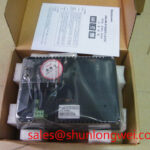
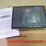
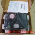
MT510LV4CN AUO Industrial TFT LCD HMI Panel
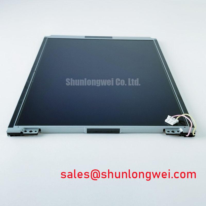
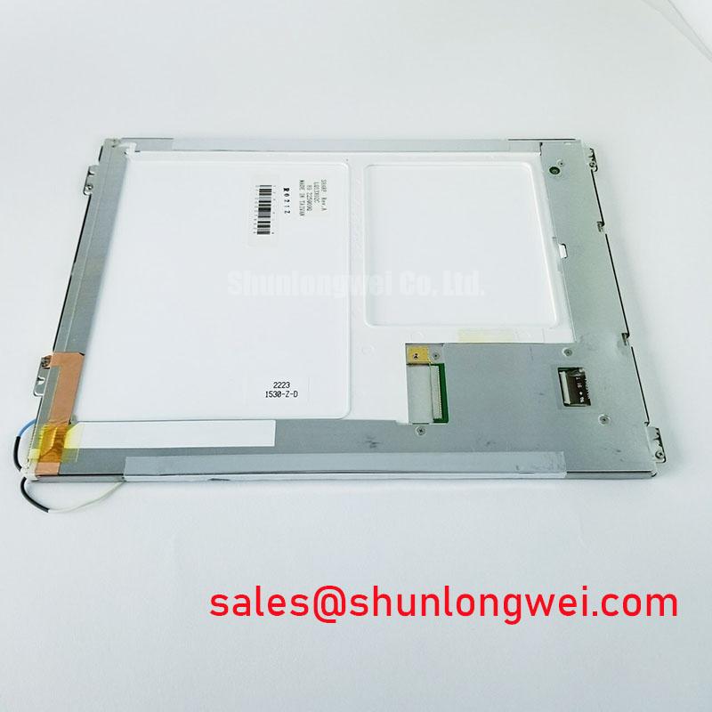
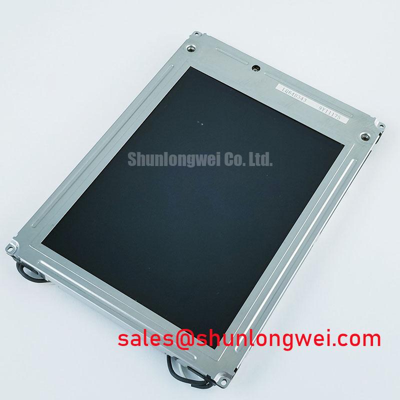
Before installation, inspect the MT510LV4CN TFT LCD module for connector damage, bezel deformation, contamination, and uneven mounting surfaces, then compare the replacement unit with the original panel documentation.
The MT510LV4CN is an AUO industrial grade LCD and HMI panel module intended for evaluation in equipment such as industrial operator interfaces, automated guided vehicle displays, and forklift telematics screens. Its supplied factory classification identifies it as a TFT LCD Display Module. The available product record marks the factory specification status as verified, while detailed electrical timing, optical, dimensional, and interface values must be confirmed against the original equipment documentation before system integration.
| Parameter | Specification Status |
|---|---|
| Model | MT510LV4CN |
| Manufacturer | AUO |
| Product category | Industrial Grade LCD and HMI Panel |
| Module construction | TFT LCD Display Module |
| Factory specification status | Official Factory Spec Verified |
| Panel dimensions, resolution, interface, and supply voltage | Verify from the original panel documentation |
Preventing Frame Lag and Image Smearing in Cold Storage and Outdoor Industrial Facilities
When the MT510LV4CN is assessed for a cold storage interface, outdoor control station, AGV terminal, or forklift display, the first check should be the actual operating temperature requirement stated by the equipment manufacturer. The available product information does not provide a confirmed operating temperature range, gray to gray response value, contrast ratio, sunlight readability rating, or anti glare coating specification for this model. Those values should not be inferred from the industrial category alone.
At sub zero temperatures, liquid crystal response can become slower because viscosity changes affect pixel transition behavior. A technician evaluating image persistence should compare the panel with a known good display using the same video source, refresh conditions, brightness setting, and enclosure temperature. A slow transition may also involve the host graphics path, signal timing, cable quality, or temperature dependent power regulation, so a single observed symptom should not be assigned to the panel without checking the complete signal chain.
Outdoor installation requires a separate optical assessment. Direct sunlight, viewing angle, enclosure reflection, and protective cover transmission can alter perceived contrast. The supplied information does not verify a contrast ratio above any particular value at a specified illumination level, nor does it confirm an anti glare surface. Integrators should therefore evaluate the finished display assembly under the intended lighting conditions rather than relying on the module category.
Thermal cycling also places attention on the bezel, sealing interface, cable exit, and enclosure ventilation. Inspect for condensation after a cold to warm transition and allow the assembly to reach a stable condition before applying power. The enclosure design should control moisture entry without trapping heat around the panel. Engineers reviewing the operating principles of TFT modules can refer to The Ultimate Guide to Industrial TFT LCD Technology when comparing panel technologies and common integration issues.
Industrial Bezel Mechanical Envelope Tolerances and Mounting Screw Torque Optimization
The MT510LV4CN should be installed only in a chassis that matches the original mechanical drawing. The supplied factory data does not include outer bezel dimensions, active area dimensions, mounting hole locations, panel thickness, or fastener specification. These values are essential for an AGV or forklift display because vibration loads can be transferred unevenly when the cutout or support frame is incorrect.
As a general Design Consideration, the mounting frame should support the panel evenly without forcing the bezel into a twisted position. Fasteners should be tightened in a gradual cross pattern where the mechanical drawing permits it, with the final torque determined by the specified screw size, thread material, bracket construction, and panel manufacturer instructions. The commonly used torque value for another assembly must not be presented as an official value for this AUO model.
Localized pressure can produce temporary optical nonuniformity, visible dark areas, or mechanical stress near the display perimeter. If the image changes when the bezel is pressed, loosen the mechanical load and inspect the frame flatness before changing electrical settings. Do not attempt to correct a mechanical strain problem by increasing brightness or altering the video source.
TTL and LVDS are not interchangeable assumptions for this product record. The system integrator should verify the actual signal interface, pin assignment, color mapping, clock arrangement, data hold requirements, and cable orientation from the original panel documentation. A replacement cable should be selected by confirmed pin compatibility, not by connector appearance alone.
Maintenance Note: Inspect the display support frame, sealing gasket, ventilation path, and cable strain relief during scheduled service so that vibration, dust, and thermal expansion do not create progressive mechanical loading.
Backlight Driving, Dimming, and Flicker Evaluation
Backlight technology is not identified in the supplied official product parameters for the MT510LV4CN. The system integrator should verify whether the original assembly uses an integrated backlight, a separate driver board, or another arrangement before applying power. It is not technically safe to assume LED or CCFL operation from the TFT LCD category alone.
If the original system uses an LED backlight, the driver must be matched to the documented backlight connection, current requirement, enable behavior, and dimming method. If it uses a high voltage lamp arrangement, the service procedure and insulation requirements will be different. The replacement decision should be based on the original panel and system documentation rather than a generic display wiring diagram.
Flicker evaluation should be performed with the display installed in its intended control system. Check brightness changes at several operating levels, observe the screen through a camera only as a secondary diagnostic method, and compare the result with direct visual inspection. Driver ripple, PWM frequency, grounding, cable routing, and interaction with the host power supply can all influence perceived flicker. No PWM frequency, duty cycle linearity, backlight lifetime, or half brightness lifetime is confirmed in the provided MT510LV4CN data, so those figures require source documentation before being used in a purchase or design specification.
For AGV and forklift telematics applications, the backlight control interface should also be checked during machine start, battery voltage variation, and low temperature operation. A display that appears stable on a bench supply may behave differently when the vehicle DC system shares loads with motors, communications equipment, or warning devices. Designers should verify the complete power path, transient behavior, connector retention, and conducted noise during an installed equipment test.
Display Interface Synchronization and Logic Power Rail Verification
Before connecting the MT510LV4CN, identify the panel interface from the original AUO documentation and compare every signal position with the host controller. The available product record does not confirm a TTL 24 bit RGB bus, an LVDS interface, a logic supply voltage, power on timing, JEIDA mapping, VESA mapping, or a differential impedance requirement. These details must be measured or verified from the correct technical document for the exact panel revision.
Split images, incorrect colors, unstable text, or a blank screen can involve incorrect mapping, reversed cable orientation, missing enable control, timing incompatibility, inadequate grounding, or an unsuitable power rail. Troubleshooting should begin with power off inspection, connector keying, cable continuity, and host configuration. With the equipment powered under controlled conditions, compare the panel supply behavior and display timing with the known good configuration. An oscilloscope can help verify clock and data integrity against the original signal path, but probe loading and grounding technique should be considered when interpreting the result.
The logic supply should be taken from the original panel documentation rather than selected from a general LCD voltage list. The same caution applies to power sequencing. The controller, backlight enable, reset behavior, and panel logic may require a defined order, but no timing interval is officially supplied here for the MT510LV4CN. System engineers should validate startup and shutdown behavior across the intended temperature and input voltage conditions.
For vehicle mounted displays, route high current motor and actuator wiring separately from sensitive display cables where the enclosure allows. Minimize unnecessary loop area, provide appropriate cable retention, and verify the display while the vehicle performs representative acceleration, braking, communication, and charging events. If an image fault appears only during a machine event, compare the panel supply and video signals at the same instant rather than assuming an internal display failure.
The MT510LV4CN is documented here as an AUO industrial TFT LCD display module. Dimensions, resolution, interface type, electrical ratings, optical performance, backlight architecture, and environmental limits remain items for confirmation against the original panel documentation before final equipment approval.