
Content last revised on September 23, 2026
Backlight and Display Signal Troubleshooting
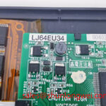
The available factory identification confirms the LJ64EU34 as a Sharp TFT LCD display module, but it does not establish the panel’s illumination technology, backlight electrical ratings, dimming method, interface type, or timing limits. The system integrator should verify the required supply voltage, backlight arrangement, control signals, and connector assignment from the original panel documentation and the equipment schematic.
During a black screen investigation, isolate the display chain methodically. Confirm that the host controller starts correctly, that the cable is fully seated at both ends, and that the panel receives the required power sequence defined by the original equipment. If the equipment uses a separate illumination driver, inspect its enable and brightness control signals with suitable test equipment while comparing results to a known good signal path. A missing enable command, damaged cable conductor, unstable supply, or controller fault can each produce similar visible symptoms.
Constant current LED drivers, PWM dimming, and high voltage CCFL inverters are different system architectures. They must not be attributed to this specific Sharp module without supporting documentation. As a Design Consideration, service teams should identify the installed backlight architecture before probing the circuit, since high voltage illumination circuits require different handling and measurement practices from low voltage LED driver stages.
For systems using TTL or LVDS video transmission, clock stability and data timing are host board characteristics that should be checked against the original panel timing requirements. Image dropouts that change when the cable is moved may indicate a cable, connector, grounding, or signal integrity issue. They do not independently prove a panel fault.
Brightness and Backlight Reliability Assessment
Brightness consistency should be evaluated as an observed operating condition, not as a declared lifetime rating for the LJ64EU34. No LED life, L70, B50, luminance, or thermal specification is provided in the verified product information available here. It would therefore be inaccurate to assign a service life figure, constant luminance capability, or illumination reliability value to this exact model.
When a display remains readable but appears dimmer than the original installation, compare the panel with a known working assembly under the same host settings. Confirm the equipment brightness command, illumination power stage, cable condition, panel surface cleanliness, and any enclosure obstruction that could affect thermal behavior. A brightness change may arise from several parts of the display system, and replacement decisions should follow measured evidence rather than a single visual symptom.
As a Design Consideration, enclosure designers commonly avoid concentrating heat along display edges and avoid loading the panel frame unevenly. The required mounting arrangement, thermal path, sealing method, and environmental qualification remain system determined. No mounting torque, thermal interface material, or edge rail arrangement should be assumed for this model unless the original equipment documentation specifies it.
For broader engineering guidance on industrial display integration, environmental exposure, and HMI maintenance planning, consult the Industrial Display & HMI Solutions resource. Sharp’s Display Solutions official portal is also a useful manufacturer reference when confirming display technology documentation and product family information.
Potential use in surgical navigation or ultrasound diagnostic display equipment requires a separate compatibility assessment. The host system owner should verify image quality requirements, mechanical fit, interface compatibility, enclosure conditions, and any equipment level regulatory obligations. The panel alone must not be represented as independently compliant with a complete medical display system requirement.
Display Cable Routing and Signal Integrity Checks
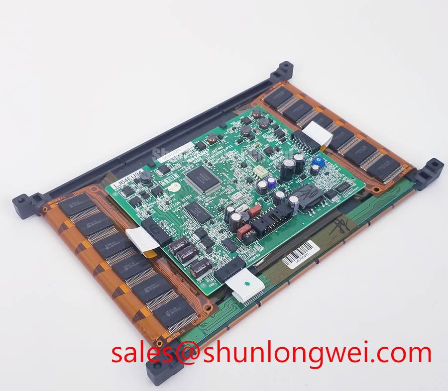
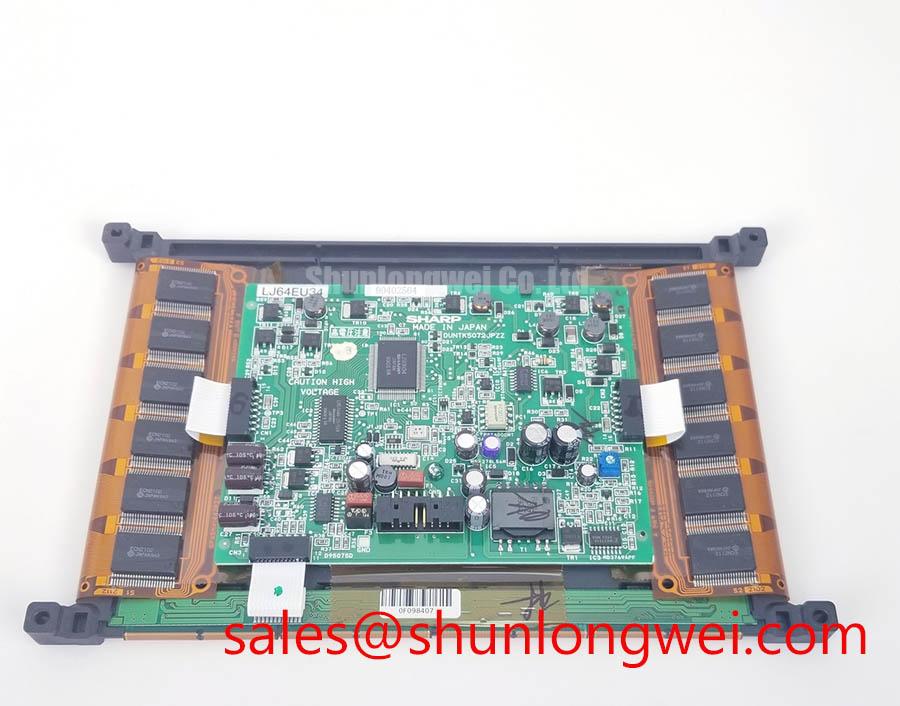
Before connecting a replacement LJ64EU34, compare the original panel connector orientation, pin count, keyed location, cable exit direction, and mechanical envelope. These checks protect against a mistaken assumption that panels with a similar appearance share the same electrical interface. The available verified information identifies a TFT LCD module only; it does not confirm a particular differential signaling standard, data mapping arrangement, logic voltage, or power-on timing requirement.
Where the host equipment uses differential video signaling, controlled impedance, pair continuity, shielding, and matched routing are Design Considerations for the equipment assembly. Their exact targets are established by the display interface standard, cable construction, transmitter characteristics, receiver characteristics, and the original panel documentation. Engineers should inspect the signal path with appropriate instruments and verify waveform quality against the known good equipment condition.
Split images, color displacement, vertical artifacts, and intermittent lines can result from connector contact condition, damaged conductors, controller board faults, incorrect configuration, or signal integrity degradation. Check whether the symptom follows the panel, the cable, or the host controller. This comparison is often more useful than attempting to assign one visible fault to one assumed cause.
When a replacement assessment requires a same class display for comparison, the LM057QC1T08 can be reviewed as a separate product record. It should be evaluated independently for physical dimensions, interface, timing, mounting, optical requirements, and equipment documentation compatibility. Similar category placement does not establish electrical interchangeability.
Display Signal Integrity and Noise Checks in High-Vibration Bays
In equipment located near motors, switching power stages, relays, or moving mechanisms, inspect the full display harness before attributing pixel jitter or horizontal noise bands to the panel. Verify connector locking, cable strain relief, chassis bonding, grounding continuity, and routing separation from known noise sources. Shield termination and common mode suppression are system level design choices that should be validated in the installed equipment.
High vibration can gradually affect connector retention and cable contact consistency. With power removed, examine the cable path for pinch points, sharp bends, abrasion, and tension at the connector. With the equipment operating under controlled service conditions, compare display behavior while observing the video output and supplies. If a disturbance is present at the source or changes with harness movement, further testing should focus on the host path before a module replacement is finalized.
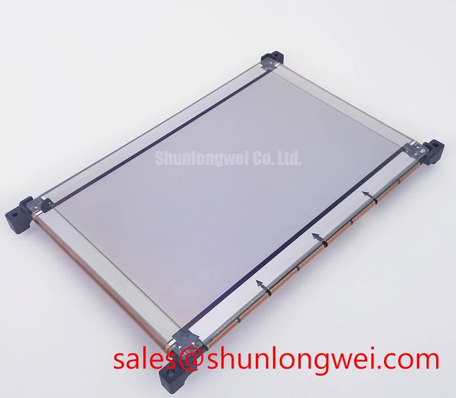
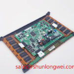
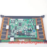
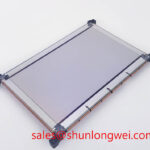
The LJ64EU34 Sharp TFT LCD Display Module should be integrated only after confirming the original equipment electrical documentation and mechanical arrangement. This approach supports practical maintenance work while keeping the decision grounded in the verified product identity rather than unconfirmed assumptions about backlight technology, signal format, operating life, or system certification.