



Content last revised on September 23, 2026
Backlight Luminance and Lifetime Verification
With power removed, first inspect the LQ64D343 display connector lock, flex routing, and logic supply pins before reconnecting the panel to a machine controller. Measure the logic rail at the panel power pins with a digital multimeter and verify that it remains within the official 3.3V / 5.0V ± 0.5V logic supply specification. A white screen, unstable image, absent graphics, or driver latch up can be associated with an incorrect or poorly regulated logic supply, although the complete signal path and host board must also be checked.
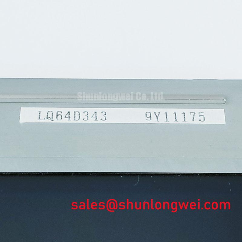
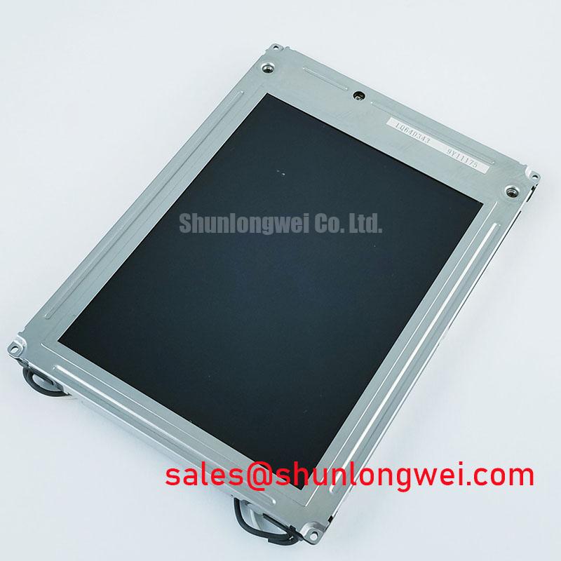
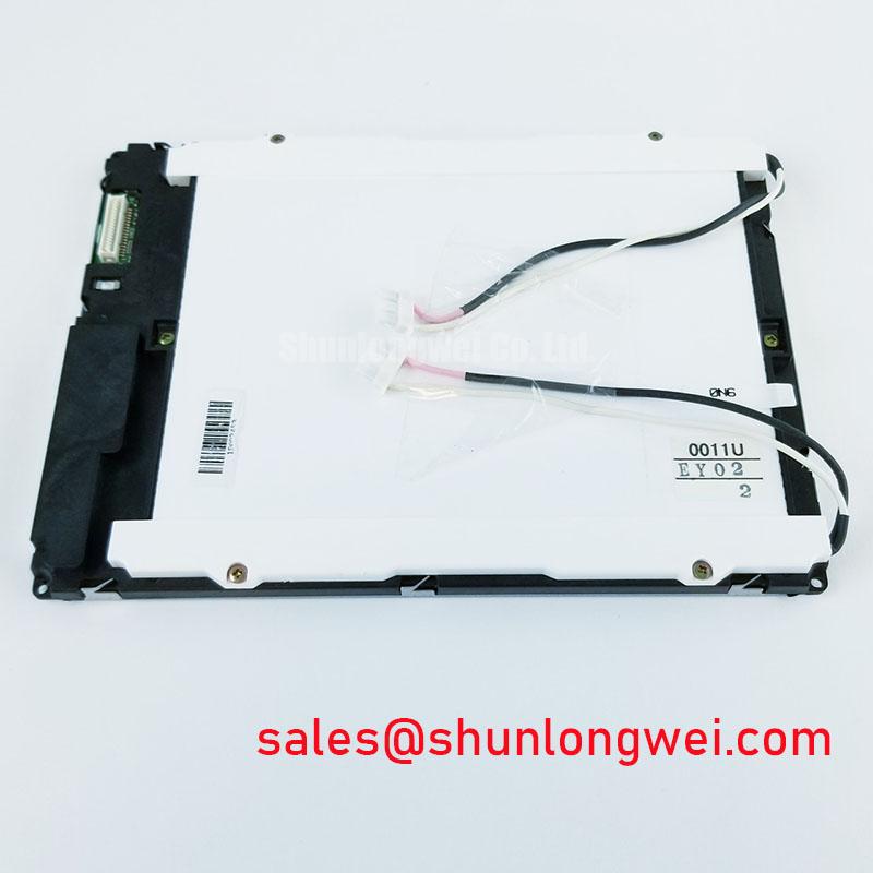
The LQ64D343 is a Sharp LCD display used in equipment where an existing display assembly must be evaluated against the original electrical and mechanical integration conditions. Its official backlight lifetime specification is more than 50,000 hours typical, defined at more than 50 percent of initial brightness. This value supports service planning, but it does not replace an on equipment luminance check because enclosure temperature, operating schedule, driver behavior, and optical contamination remain system dependent.
| Parameter | Specified Value | Classification | Practical Verification |
|---|---|---|---|
| Logic supply voltage | 3.3V / 5.0V ± 0.5V | Official Datasheet Specification | Measure at logic power pins with a digital multimeter |
| Differential line impedance | 100 Ω ± 10% | Design Consideration | Verify differential routing with TDR where board analysis is required |
| Chassis screw torque | 0.35 to 0.45 N·m | Design Consideration for M3 fasteners | Use a calibrated digital torque screwdriver |
| Backlight lifetime | More than 50,000 hours typical | Official Datasheet Specification | Compare luminance against the initial installation baseline |
For an LQ64D343 installation showing a dim image, begin by separating image generation from illumination. View the panel at an angle under controlled ambient light and determine whether the LCD is producing a faint image with inadequate illumination or whether graphics are missing altogether. Then check the host equipment’s display power path, connector engagement, and any backlight control signals documented by the original equipment manufacturer. This avoids replacing a panel when a damaged cable, loosened latch, or power board condition is the actual issue.
The official lifetime statement for this Sharp display is more than 50,000 hours typical to more than 50 percent of initial brightness. It should not be converted into an L70 or B50 rating, a guaranteed operating interval, or a field failure prediction because those values are not provided in the available official product parameters. A photometer comparison against a known service baseline is more useful than visual judgment alone, particularly where the display is used for long periods with static HMI pages.
Constant luminance is determined by the full assembly rather than by the LCD alone. As a Design Consideration, heat spreading around narrow display edges should avoid creating localized pressure or concentrated heat near the optical area. The enclosure designer should verify thermal behavior with the final backplate, gasket, mounting arrangement, and duty cycle. Do not assume a specific internal light guide material, LED configuration, anti glare treatment, sunlight readability figure, or contrast ratio unless these are documented for the exact panel and its installed optical stack.
Where a marine radar or navigation bridge console is being assessed, direct ambient light, salt exposure at the enclosure level, and long static screen intervals are conditions that the system integrator should review separately. The LQ64D343 official data supplied here does not state a 500:1 contrast ratio at 50,000 lux, nor does it establish an anti glare coating specification. Engineers should validate actual display legibility using the installed enclosure, front window, viewing angle, and site lighting conditions.
Static interface content can also make gradual brightness loss more noticeable. Design Consideration: rotate seldom changing status elements where the control system permits, maintain sensible screen blanking behavior, and check whether apparent retention changes after normal image content returns. Such observations can help distinguish a display condition from a software image, video timing, or operator interface configuration issue, but they do not establish a single root cause without controlled testing.
Radiated Emissions and Grounding Considerations
When pixel jitter, intermittent horizontal sparkle, or noise bands appear while nearby motor equipment is active, inspect the physical signal route before altering controller settings. Check that the display cable is fully seated, that the connector lock is closed as intended by the cable assembly, and that the cable has not been repeatedly bent at the connector exit. Flex damage can be intermittent and may only appear when the cabinet door moves, vibration changes, or the cable is disturbed during servicing.
The relevant signal integrity target is 100 Ω ± 10% differential line impedance, identified as a Design Consideration. This figure applies to the differential signal path evaluation and can be checked by time domain reflectometry when a board level routing concern is suspected. Impedance discontinuities, unsuitable cable treatment, or poor shield termination may contribute to pixel instability or radiated noise, but measurement against a known good signal path is needed before attributing the symptom to one cause.
Shield continuity and backplate grounding are installation level concerns, not independent compliance claims for the LQ64D343. A 360 degree shield termination, common mode suppression, and a multi point grounding approach may be assessed by the equipment designer when cable borne interference is suspected. Their usefulness depends on the complete cabinet layout, drive switching environment, grounding architecture, cable length, and enclosure construction. The system team must perform relevant emissions and immunity testing on the completed equipment; this display alone is not presented as independently compliant with CISPR Class A or Class B requirements.
A skew budget of 50 ps is sometimes used as a high speed interface Design Consideration, yet it is not an official specification supplied for this LQ64D343 display. Engineers should instead confirm the original host interface documentation and use oscilloscope measurements only where access, probe loading, and a reference signal path permit meaningful comparison. If the installed cable is routed close to a 400V variable frequency drive, improve separation and preserve the intended shield path, then verify the result under actual machine operating conditions.
⚠️ Field Alert: Disconnect equipment power and allow stored energy to discharge before inserting or removing the display cable, because live connector handling can expose signal pins to unintended voltage differentials.
For broader enclosure, grounding, and industrial HMI integration context, the Industrial Display & HMI Solutions guide can be used alongside the original equipment documentation. It should support a system evaluation rather than replace the exact panel pinout, power sequence, or cable requirements of the equipment under repair.
Flush Mount Open Frame Bezel Integration and Perimeter Gasket Considerations
Before fastening an LQ64D343 into a flush mount opening, place the panel in its intended position and confirm that the bezel, support points, cable bend path, and surrounding hardware do not load the active display area. A dark patch, local brightness variation, or perimeter mura observed after installation can be related to uneven mechanical stress, but the panel should also be checked outside the final enclosure when practical. That comparison helps separate mounting induced optical effects from source image or illumination conditions.
For M3 chassis fasteners, the stated 0.35 to 0.45 N·m range is a Design Consideration, not an official Sharp mounting requirement provided in the available parameters. Use a cross pattern and a calibrated torque screwdriver to promote even clamping. The final torque, screw length, washer selection, gasket compression, bezel flatness, and mounting sequence must be verified by the system integrator against the original equipment’s mechanical drawing. Excessive local clamping can distort the cell gap and lead to visible perimeter optical mura defects.
Perimeter gaskets can isolate the display from cabinet vibration and prevent direct metal contact where an enclosure design calls for them. Their material, thickness, compression behavior, and environmental compatibility are not specified for this model in the supplied official data. Avoid assuming a particular gasket composition or compression ratio. Instead, assess whether the completed assembly keeps load away from the viewing area while maintaining a stable interface under the vibration and shock conditions relevant to the host equipment.
Repeated flexing of a display cable deserves particular attention during maintenance. A cable that is tight at the connector, trapped beneath a bezel, or forced through a sharp chassis edge can lose reliable contact over time. Route the cable with enough freedom for panel service, secure it so it cannot rub against moving hardware, and verify the locking feature after the bezel is fitted. The exact minimum bend radius must come from the original cable documentation rather than a generic panel rule.
For a potential replacement assessment, LM057QC1T08 can be reviewed as a comparison reference. Mechanical envelope, connector position, pin assignment, logic supply requirement, timing, optical behavior, and mounting conditions must all be validated against the original LQ64D343 installation before any substitution decision is made.
Optical Luminance Degradation and Backlight Retrofit Pathways
Do not infer the LQ64D343 backlight technology from its lifetime specification alone. The official information supplied for this product confirms a typical lifetime of more than 50,000 hours to more than 50 percent of initial brightness, but it does not identify the lamp type, ignition voltage, dimming method, PWM ratio, or driver topology. Any repair plan involving a backlight inverter, constant current LED driver, or modernization assembly must therefore begin with the original panel and host system documentation.
For equipment with a dim screen, record the observed condition before replacing parts. Compare brightness between startup and normal operating temperature, inspect connectors and cable strain relief, verify the logic rail, and check the display source with a known good signal path if one is available. If the image is stable while luminance declines, the condition may involve the illumination path or its supply. If the image itself is unstable, logic power, signal integrity, cable seating, or the host controller may also require investigation. These are diagnostic branches, not definitive one symptom to one cause rules.
A CCFL to LED retrofit cannot be treated as a direct change based on general display practice. Claims of cold ignition voltage, acoustic noise suppression, specific dimming ratios, or projected service life require documentation for the exact retrofit hardware and complete assembly. The system integrator should verify physical clearance, panel optical coupling, supply capacity, thermal behavior, control compatibility, and safety requirements before modifying an existing display system.
Where bright ambient conditions affect a radar or navigation bridge console, verify the actual installed display’s luminance, contrast stability, viewing condition, and front window treatment rather than relying on generic sunlight readability language. The official parameters available for the LQ64D343 do not provide a direct sunlight contrast specification or an anti glare coating rating. A controlled comparison with the operational console, original display settings, and representative ambient light provides a more defensible basis for repair or replacement evaluation.