







Content last revised on September 13, 2026
Edge Lighting Thermal Review and Light Guide Preservation Checks
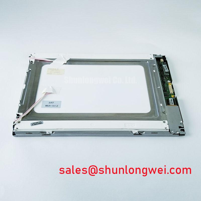
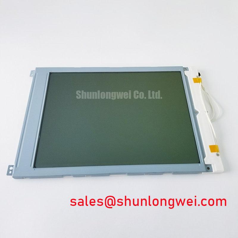
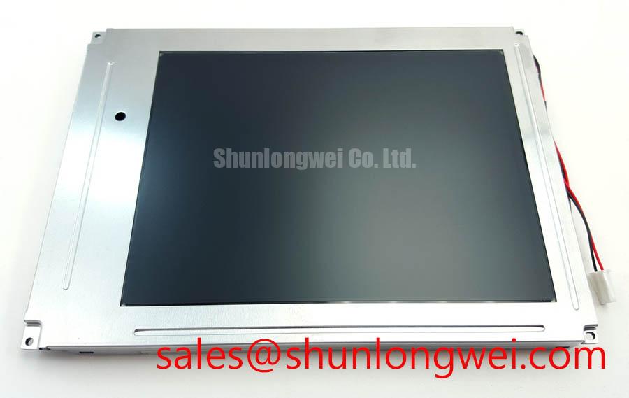
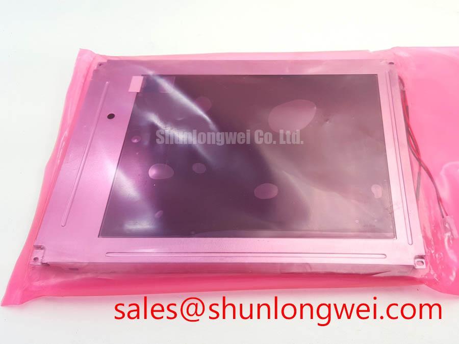
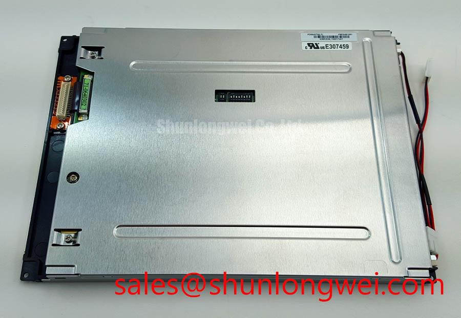
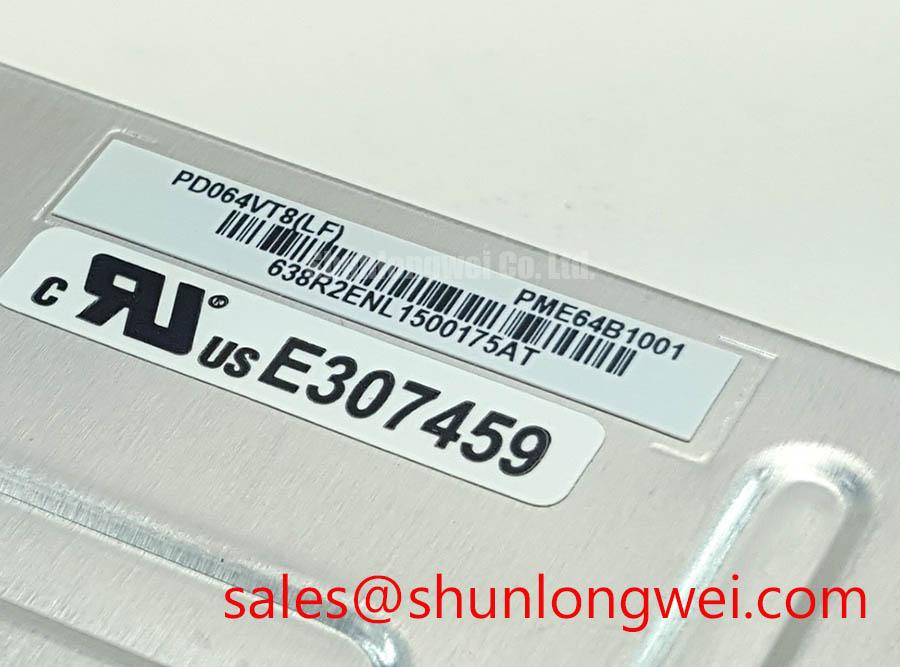
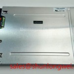
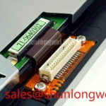
Before connecting the replacement display, inspect the PD064VT8 for enclosure damage, check the connector area under magnification, and compare the original panel’s label with the system documentation. The supplied factory record identifies this part as a PVI (Prime View International) TFT LCD Display Module for industrial LCD and HMI use, but it does not provide numerical values for resolution, active area, luminance, viewing angle, interface, supply voltage, backlight type, or environmental ratings. Those items must be confirmed against the original panel documentation before installation.
The PD064VT8 is identified as a TFT LCD display module, while the supplied official parameter record does not confirm whether its backlight is LED, CCFL, or another arrangement. Do not infer the backlight architecture from the panel appearance alone. The system integrator should verify the original display documentation, connector pinout, backlight driver requirements, enable signal, dimming method, and current limits before applying power.
For a telematics display in a heavy mining shovel or earthmoving equipment cab, the mechanical frame should support the panel evenly around its approved mounting points. A narrow contact area or uneven compression can place stress on the glass and may create optical nonuniformity after installation. Use a clean, stable support surface and keep the display away from direct contact with metal edges, cable clamps, and fastener heads.
Where the equipment uses a separate backlight driver, inspect the driver output and connector condition independently from the LCD signal path. A replacement panel should not be connected to an unverified driver simply because the connector appears mechanically compatible. Confirm pin numbering from the original panel drawing and trace power, ground, control, and signal conductors before energizing the assembly.
Heat spreading is a system level design consideration rather than a confirmed feature of this model. If the enclosure contains a high power backlight or limited airflow, designers should evaluate local temperature rise around the display edges and driver components. The final thermal arrangement should be validated under the actual enclosure, brightness setting, ambient temperature, and duty cycle. The supplied record does not specify a luminance rating, LED lifetime, L70 value, B50 value, or backlight temperature limit for the PD064VT8.
Fuse coordination also remains system determined. The available factory information contains no fuse rating or I²t coordination table for this display module. The protection device should therefore be selected from the documented input characteristics of the complete display assembly and its driver, with inrush and fault behavior checked during bench testing. Power should remain disconnected while the panel cable is being inserted or removed.
Humidity Storage and Delamination Prevention Checks
The supplied factory specification identifies the PD064VT8 as an industrial grade LCD and HMI panel, but it does not state a storage humidity limit, operating humidity limit, condensation allowance, sealing specification, or approved thermal cycle range. It would be unsafe to describe the module as qualified for a particular high humidity test such as 60°C and 90% RH without a supporting PVI document.
For incoming inspection, allow a panel that has been moved from a cold warehouse to reach the inspection room before energizing it. Examine the bezel, glass perimeter, connector reinforcement, and visible seal areas for moisture, contamination, or mechanical disturbance. Any condensation should be treated as a handling condition requiring controlled stabilization, not as evidence of a display failure.
Low temperature operation can alter liquid crystal response, but the supplied record does not state the liquid crystal operating range, gray to gray response time, contrast behavior, or image quality at sub zero temperature. If this panel is evaluated for equipment exposed to outdoor conditions, the integrator should test startup, grayscale transitions, refresh behavior, and image retention across the actual enclosure temperature profile.
Perimeter adhesive and display sealing should be considered part of the complete mechanical assembly. The product information provided does not confirm the adhesive chemistry, seal construction, or resistance to pressure washing, dust ingress, vibration, or chemical exposure. For a cab mounted telematics display, enclosure sealing, venting, shock isolation, and cable strain relief must be evaluated at system level.
When a replacement panel is installed, record the original cable routing before removal. Avoid bending the flexible cable across a sharp corner or placing it beneath a clamp intended for heavier wiring. Connector retention should be checked after the first mechanical vibration test, because a display that passes a static bench test can still experience intermittent signal loss if the cable is not supported correctly.
| Item | PD064VT8 information available in the supplied factory record | Engineering action |
|---|---|---|
| Manufacturer | PVI (Prime View International) | Match the replacement label with the equipment service record |
| Product category | Industrial Grade LCD/HMI Panel | Confirm the complete system interface before installation |
| Construction category | TFT LCD Display Module | Verify mounting, cable routing, and enclosure compatibility |
| Humidity and thermal limits | Not supplied | Obtain the original panel documentation and perform system validation |
| Backlight specification | Not supplied | Verify the required driver and control method from the original assembly |
Surface Glare and Ambient Readability Evaluation
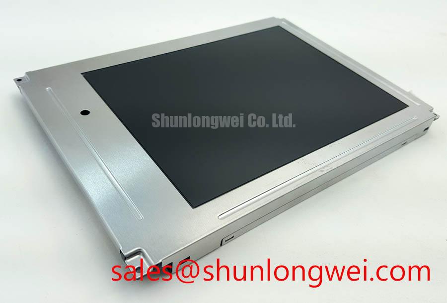
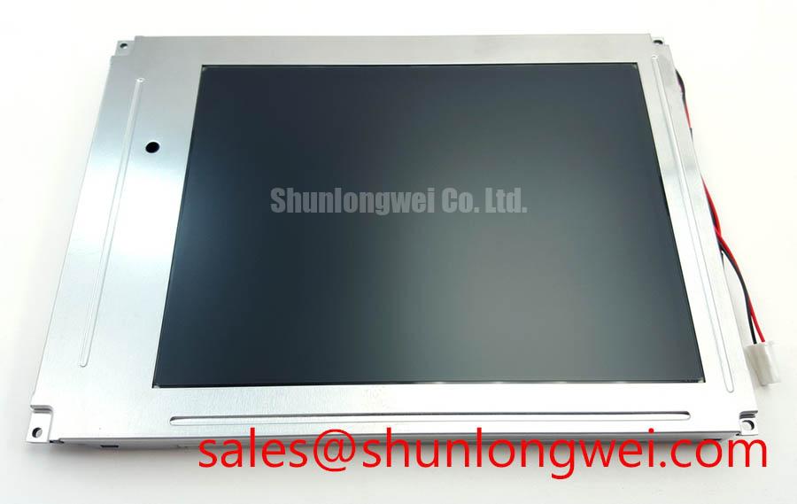
The supplied information does not confirm an anti glare coating, anti reflective coating, etched surface, optical bonding arrangement, contrast ratio, viewing angle, or luminance value for the PD064VT8. These characteristics should not be inferred from the TFT LCD category. A field replacement should be assessed with the actual display window, cab lighting, protective cover, and viewing position used by the operator.
During incoming inspection, display a series of full screen test images including white, black, red, green, blue, gray ramps, and fine text. Inspect the panel from the expected operator position and from practical off axis positions. Look for persistent dark points, bright points, line defects, uneven illumination, color shift, and regions that change appearance when the viewing angle changes. Record the result against the customer’s approved acceptance criteria rather than applying an unverified model specific threshold.
Ambient light evaluation should include the transparent cover and any touch interface that will remain in front of the LCD. Reflections can originate from several surfaces in the assembled HMI, so a panel that appears acceptable on an open bench may perform differently after installation. If readability is marginal, the system team should review lighting direction, visor geometry, window finish, display brightness, and operator viewing angle before changing the panel.
The optical response of a display is governed by its panel construction and drive conditions. General optoelectronic principles can be reviewed through the Optoelectronics reference, but that industry reference does not establish specifications for the PD064VT8. Likewise, the display technology background in The Ultimate Guide to Industrial TFT LCD Technology should be used as general engineering context, not as a substitute for the original PVI panel sheet.
For procurement comparison, engineers may also review the TCG084SVLQAPNN AN30 S as a separate display product. It should not be treated as a direct replacement until dimensions, connector position, electrical interface, optical performance, mounting pattern, and firmware compatibility have been checked against the equipment documentation.
💡 Bench Tip: Use ESD protection and confirm that every flexible cable is fully aligned and evenly latched before applying power.
Backlight Driver and Dimming Compatibility Verification
The factory record supplied for the PD064VT8 does not confirm a WLED backlight, constant current input, PWM dimming ratio, acoustic behavior, half life, MTBF, or CCFL ignition requirement. Claims such as 1000:1 dimming, greater than 50,000 hour operation, or a specific ignition voltage must therefore be excluded unless they are stated in the original PVI documentation for this exact model and revision.
Begin the electrical check by identifying the original panel’s power and backlight connectors separately from the video interface. Confirm the connector keying, pin numbering, supply voltage, enable polarity, brightness control signal, and return paths using the equipment schematic or panel datasheet. The system integrator should verify the required supply voltage from the original panel documentation rather than selecting a value from a similar looking display.
If a dedicated backlight driver is retained, measure its output only with suitable test equipment and within the driver manufacturer’s stated operating conditions. An unexpected display result may involve the panel, driver, cable, control signal, grounding, or power sequencing. Compare the suspected channel with a known good signal path and use an oscilloscope where necessary instead of assigning a single cause from the visual symptom alone.
Flicker assessment should be performed at the real brightness settings used by the operator. Observe low brightness operation, camera recorded images, and rapid changes in brightness command. If the equipment uses PWM, the controller frequency, duty cycle, enable timing, and driver response must be verified as a complete system. The supplied PD064VT8 record does not establish a model specific PWM frequency or dimming depth.
Signal integrity also depends on cable length, shielding, connector condition, grounding, and the host controller. Minimize unnecessary loop area and protect the display cable from high current switching conductors, while allowing the system engineer to verify the result through eye pattern, timing, and conducted noise measurements. Information published by SanRex can provide general reference material for power semiconductor switching environments, but it does not define the LCD interface or qualification status of the PD064VT8.
Before releasing a replacement to service, document the panel identity, visual inspection result, connector inspection, full screen test, brightness response, and power up behavior. The supplied official factory context supports identification of the PVI PD064VT8 as an industrial TFT LCD display module. Electrical, optical, environmental, and mechanical acceptance should be completed against the original equipment documentation and the actual telematics display assembly.