Content last revised on October 13, 2026
Radiated Emissions Compliance via Backplate Multi-Point Star Grounding
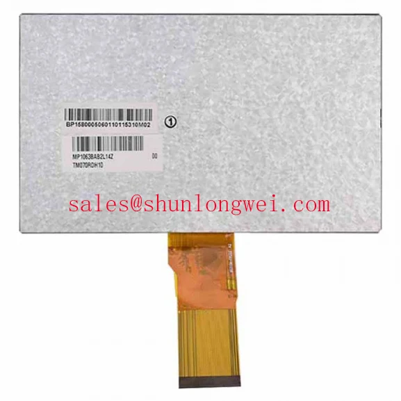
When pixel jitter or horizontal noise appears beside a variable-frequency motor drive, begin by separating display-panel behavior from cable and enclosure coupling. The TM070RDH10-53 is identified as a Tianma TFT-LCD active matrix color display module, but the available product classification does not establish an independent CISPR Class A or Class B certification for the panel itself. EMC performance therefore remains a system-level result governed by the host controller, cable assembly, backplate, power architecture, and enclosure.
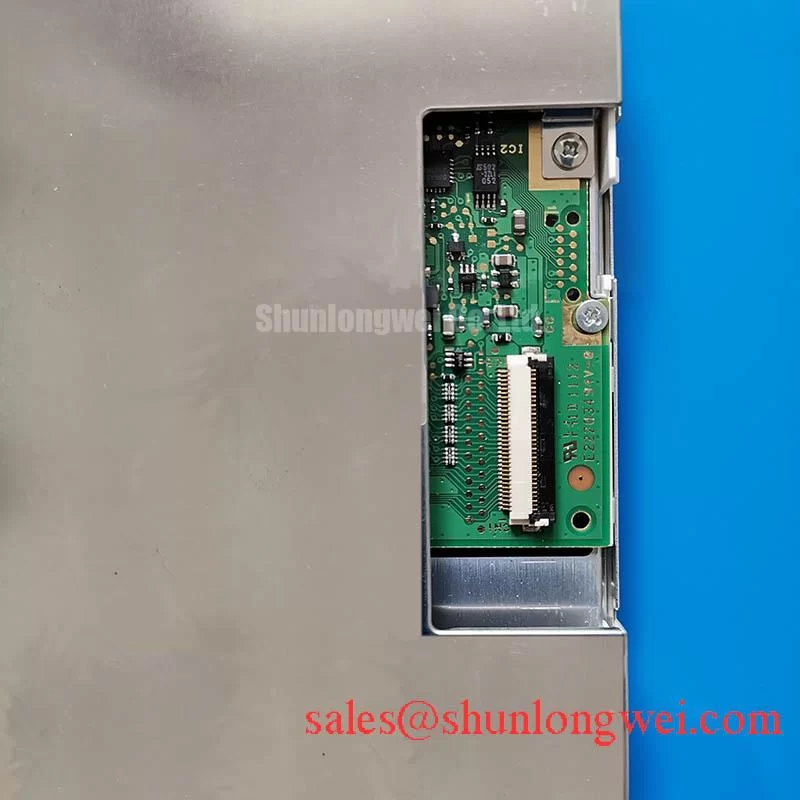
A practical inspection starts with the display cable routing. Keep high-current switching conductors physically separated from the display signal path, avoid unnecessary cable loops, and inspect whether the connector is fully seated and mechanically supported. A shielded FFC or LVDS assembly can reduce radiated coupling when its shield termination is continuous and connected according to the host equipment’s grounding scheme. Star grounding may be evaluated at several conductive backplate points, but the final topology should follow the enclosure safety, bonding, and EMC design approved for the equipment.
Common-mode ferrite components can be considered where conducted or radiated interference is observed, although their impedance behavior must be checked against the actual signal bandwidth and cable construction. Adding suppression without measuring the signal path can increase edge distortion or create a new resonance. During testing, compare the display with the motor drive disabled and enabled, then inspect the signal waveform and panel image together. This helps distinguish source noise, grounding interaction, connector movement, and timing instability without assigning a single cause to the visible artifact.
The Tianma NLT industrial TFT-LCD display technologies resource provides useful manufacturer context for industrial display evaluation. For broader interface, optical, and integration principles, engineers can also consult The Ultimate Guide to Industrial TFT LCD Technology.
Mitigating Gray-to-Gray Response Time Escalation during Cold-Start Machine Power-Up
Cold-start evaluation should focus on the first visible frame, transitional smearing, and the stability of the controller-to-panel interface as the equipment reaches its operating condition. The product information identifies the TM070RDH10-53 as an industrial grade LCD/HMI panel, but it does not provide a verified GTG response-time curve or a manufacturer-published operating-temperature range in the supplied specification set. Those values should not be treated as assumed characteristics of this model.
Liquid-crystal response can become slower at reduced temperature because the electro-optical material responds less quickly to voltage changes. In a service laboratory, display a sequence containing dark, mid-gray, and bright transitions while recording the image at the same temperature and refresh condition used by the equipment. Observe whether the perceived lag is limited to certain gray transitions or occurs across the whole image. This distinction is useful when checking panel behavior, timing configuration, source-frame changes, and backlight interaction.
Perimeter sealing and enclosure contraction also deserve inspection in equipment exposed to repeated thermal cycling. Look for mechanical stress at the panel edge, uneven bezel pressure, or signs that the mounting frame is transferring force into the display. An optical bonding or sealed front assembly may improve resistance to dust and moisture when properly engineered, but it cannot be claimed for this model without explicit construction data. Marine radar and navigation bridge consoles should therefore be assessed as complete assemblies, including gasket compression, pressure equalization, salt exposure, and service access.
Power sequencing should be checked against the original panel documentation and host controller design. The system integrator should verify the required supply voltage, interface type, enable timing, and display initialization behavior before applying power. A cold-start image fault may involve the controller, cable, timing configuration, or panel response, so compare the startup sequence with a known-good unit when available.
Constant Luminance Output Control and LED Half-Life Verification
Uniform illumination testing should begin with a full-white image, followed by gray-field and near-black patterns that reveal edge shading, local bright areas, and optical nonuniformity. The TM070RDH10-53 is classified as a TFT-LCD active matrix color display module; the supplied product data does not confirm a specific backlight architecture, luminance rating, L70 value, B50 value, or 50,000-hour half-brightness performance claim.
For incoming quality work, record luminance at consistent positions across the active image and repeat the measurement after thermal stabilization. A narrow display edge can develop a localized temperature difference when the surrounding frame, driver electronics, or enclosure restricts heat spreading. An aluminum spreader rail may be considered as part of the equipment’s mechanical and thermal design, provided it does not load the glass, obstruct the cable, or create a conductive short path.
Do not use an assumed L70 or B50 curve as a substitute for a product-specific reliability report. Those terms describe defined test outcomes and require controlled test conditions, drive current, ambient temperature, and optical measurement criteria. A service engineer can still use trend monitoring to identify progressive brightness drift, color imbalance, or a localized hot spot. The result should be recorded as equipment test data rather than presented as an official Tianma lifetime rating.
Backlight control should be evaluated with the actual host driver and thermal enclosure. Excessive current, blocked ventilation, or uneven mechanical contact can alter luminance uniformity and accelerate optical aging. Designers should verify the display’s specified electrical interface and backlight requirements from the original panel documentation before selecting a replacement driver or modifying the cabinet.
Surface Anti-Glare and Anti-Reflective Treatment for High Ambient Readability
High-ambient readability is best checked by placing the assembled panel under the same viewing direction, illumination, and front-window conditions expected in service. The current product data does not confirm an IPS, MVA, or TN cell structure, a symmetric viewing cone, or a factory-applied AG or AR coating for TM070RDH10-53. Engineers should therefore avoid assigning a specific viewing-angle value or surface treatment without the applicable Tianma documentation.
Use a controlled test image containing neutral gray steps, saturated colors, fine text, and black borders. View the screen from the intended operator position and from practical off-axis positions while checking grayscale inversion, color shift, reflected highlights, and loss of shadow detail. A wide viewing angle can improve operator visibility, but the panel’s actual optical result depends on the cell mode, polarizer structure, cover window, adhesive stack, and enclosure geometry.
An etched anti-glare surface can reduce mirror-like reflections, while an anti-reflective treatment can reduce optical reflection through a different mechanism. These treatments may affect haze, contrast, cleaning behavior, and image sharpness. If the panel is installed behind a protective window, evaluate the complete stack rather than judging the bare module. Optical bonding may reduce an air-gap reflection in a suitably designed assembly, but bonding construction, seal performance, and moisture resistance must be established by the equipment integrator.
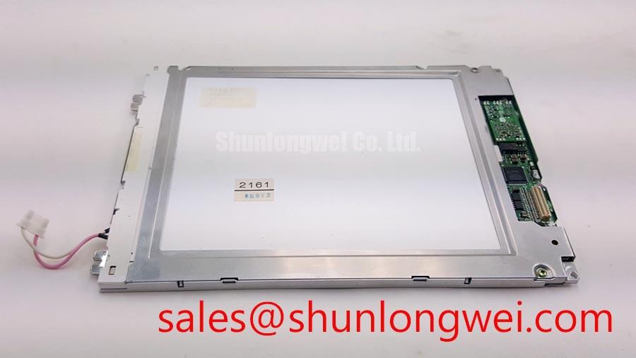
For TTL or LVDS systems, verify the transmitter clock, data timing, connector orientation, and signal quality across the intended temperature range. Do not infer interface voltage, pin assignment, or hold-time margin from the model number. When a same-size or same-resolution replacement is being investigated, the TX17D02VM2CAA-2 can be placed on the comparison list, subject to connector, mechanical, optical, and electrical compatibility checks.
💡 Bench Tip: Use ESD protection, keep the display cable aligned with the connector guide, and lock the cable flat before powering the panel.