
Content last revised on October 9, 2026
Micro-Twist Mechanical Stress Fracture Prevention on Glass Substrate Driver Bumps
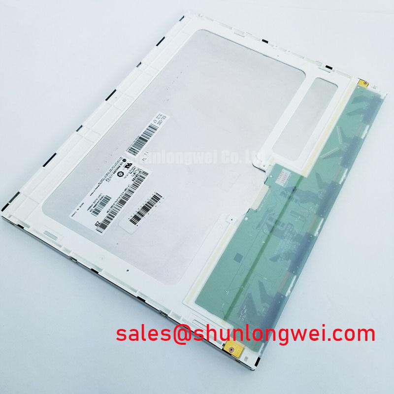
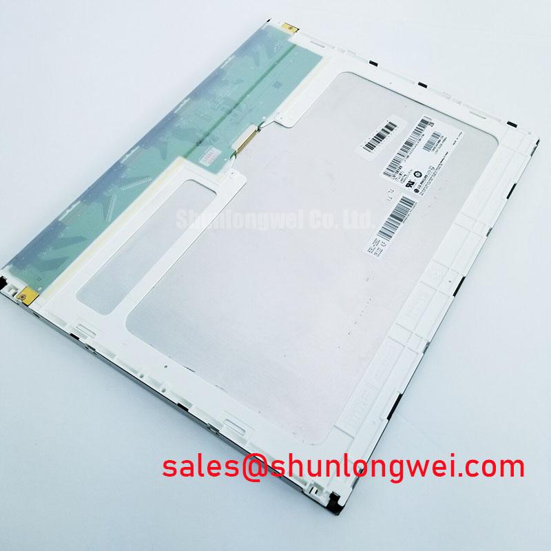
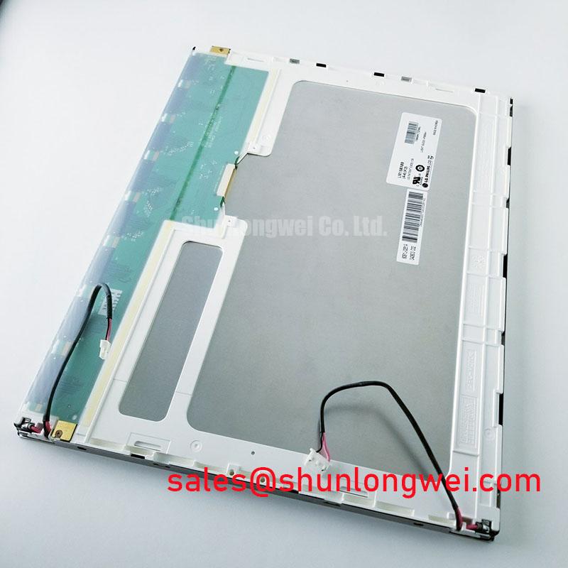
| Model | LM150X08-A3K3 |
| Manufacturer | LG Display |
| Product Category | Industrial Grade LCD/HMI Panel |
| Display Construction | TFT-LCD Active Matrix Color Display Module |
| Specification Status | Decoded Baseline / Standard Form Factor |
Begin a replacement inspection with a controlled primary-color bench test, then view the active image at a 45-degree flashlight angle to separate backlight irregularities from localized glass or driver-bond defects. Display red, green, and blue test fields individually, followed by black and white fields. A line that remains fixed across different colors deserves closer attention than a brightness variation that changes with the backlight condition.
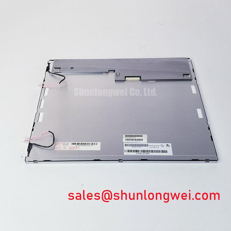
The LM150X08-A3K3 is identified as an LG Display TFT-LCD Active Matrix Color Display Module in an industrial LCD and HMI panel format. The listed product data does not establish a pixel resolution, active-area dimension, interface pinout, logic supply, or backlight technology, so those items should be matched against the removed panel and its equipment documentation before installation.
Mechanical handling is particularly important around the glass edge, flexible circuit, and bonded driver region. The panel should remain supported across its frame while the bezel or mounting plate is tightened. Uneven clamping can introduce local flexing that appears later as intermittent lines, corner shading, or pressure-sensitive image changes. Do not use the visible glass surface as a lever when positioning the module.
For a precision electronic test instrument or field analysis display, compare the replacement using fixed test images and the same viewing angle used for the original unit. If a defect disappears when the illumination changes but the signal content remains stable, inspect the backlight path and diffuser condition. If a line follows the same coordinates through multiple colors, inspect the flexible connection, connector retention, and panel seating before attributing the symptom to the display glass.
When a backlight controller uses pulse-width dimming, designers may evaluate a control range around 200 Hz to 1 kHz as a general design consideration for audible noise and visible flicker. This is not an LM150X08-A3K3 factory specification. The actual controller frequency, duty-cycle response, and acceptable optical result must be established from the installed backlight system.
VESA vs. JEIDA Data Mapping Alignment & Even/Odd Channel Signal Integrity
Check the panel interface mapping before applying power: identify the connector orientation, signal order, ground returns, enable signals, and any even or odd channel arrangement from the original equipment harness. A display can illuminate while still showing split images, reversed color order, missing vertical content, or unstable synchronization when the data mapping does not match the host timing.
The required logic supply voltage for this specific module is not included in the supplied baseline parameters. The system integrator should verify the required supply voltage from the original panel documentation and measure the host rail during startup. Avoid applying a presumed voltage simply because another industrial display uses the same connector style.
Power sequencing should be checked with an oscilloscope at the panel connector. Record the order and relative timing of the logic rail, display enable, video data, and backlight enable signals. A white screen at startup, delayed image recovery, or residual image after shutdown may result from sequencing, reset, signal integrity, or backlight control interaction. Treat the complete waveform relationship as the diagnostic evidence rather than assigning the symptom to one cause.
JEIDA and VESA mappings should be compared bit by bit with the host board configuration. Confirm color significance, clock polarity, channel order, and the allocation of even and odd data lanes. Differential routing should preserve a controlled, symmetrical path with continuous reference return. The commonly used 100 ohm differential impedance target is a general high-speed interface design consideration, not a confirmed factory value for this panel.
For outdoor-facing instruments or equipment positioned near strong ambient lighting, assess contrast stability at the actual installation angle. The anti-glare surface, cover window, bezel depth, and enclosure reflections all affect readability. Industrial display guidance from Winstar Industrial TFT-LCD and OLED Display Modules provides useful reference context for evaluating optical integration, but it does not define the specifications of this LG Display model.
Radiated Emissions Evaluation via Backplate Grounding and Shielding
Route the display cable away from noisy switching nodes and establish a deliberate shield termination strategy at the enclosure and panel backplate. A cable with broad, continuous shield contact generally provides a more predictable high-frequency return than a long pigtail. The final grounding arrangement remains a system design decision because the display module itself cannot independently establish compliance with a complete equipment EMC requirement.
When the panel is installed beside a variable-frequency motor drive or another high-current switching assembly, observe the screen while changing the machine operating state. Pixel jitter, horizontal bands, or momentary synchronization loss should be correlated with the switching event using a known-good signal path and, where practical, an oscilloscope. Inspect connector backshells, cable shield continuity, chassis bonding, and the return path before changing display settings.
Common-mode ferrite components may be evaluated as a design consideration when conducted or radiated noise couples into the display cable. Their effectiveness depends on cable construction, frequency spectrum, placement, and the available return path. They should not be treated as a standard accessory of the LM150X08-A3K3.
Backplate contact should be mechanically even and free from paint, contamination, or loose hardware where a conductive bond is required by the enclosure design. The bezel gasket must compress consistently around the display opening without twisting the frame. A good seal supports dust control and reduces mechanical movement, while the grounding arrangement should be validated through the completed equipment test plan.
For practical maintenance and integration references covering enclosure evaluation, display wiring, and harsh industrial environments, consult Industrial Display & HMI Solutions. Maintenance Note: inspect the cooling airflow path and sealing gasket condition during scheduled service so dust buildup or uneven compression does not add thermal and mechanical stress to the panel.
Solid-State WLED Constant-Current Driving, PWM Dimming & Flicker Suppression
Identify the installed backlight architecture before selecting a driver or replacement harness. The supplied product baseline confirms a TFT-LCD active matrix color display module, but it does not confirm whether the associated assembly uses a CCFL inverter, a WLED constant-current circuit, or a particular dimming interface. Do not connect a presumed LED driver or high-voltage inverter without matching the original equipment documentation and connector functions.
If the instrument uses a WLED backlight, evaluate the constant-current driver together with its enable and dimming signals. The screen should be checked at low, medium, and high brightness using both moving graphics and static measurement screens. Flicker can be influenced by PWM frequency, duty-cycle linearity, camera interaction, and the optical response of the complete display assembly. A suggested evaluation range of 200 Hz to 1 kHz may be used as a typical starting point only when it is compatible with the installed driver and the required visual performance.
Do not transfer a claimed backlight lifetime from another panel family to this model. Brightness decay depends on LED junction temperature, drive current, thermal path, duty cycle, enclosure temperature, and the manufacturer’s defined measurement method. A lifetime figure such as 50,000 hours requires a source specific to the backlight assembly and test conditions; it is not established by the baseline information for the LM150X08-A3K3.
Flexible cable routing also affects long-term serviceability. Keep the bend path free from sharp folds, avoid pulling on the connector during installation, and engage the locking mechanism evenly. Before closing the instrument, confirm that the cable is not trapped between the panel frame and chassis. After assembly, run a full-color image sequence, brightness transitions, power cycling, and a prolonged static screen test to verify that the display remains stable under the actual mechanical and thermal conditions.