

Content last revised on September 12, 2026
LM150X08-TLA1 Identification and Bench Verification
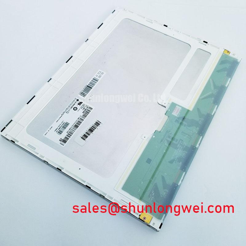
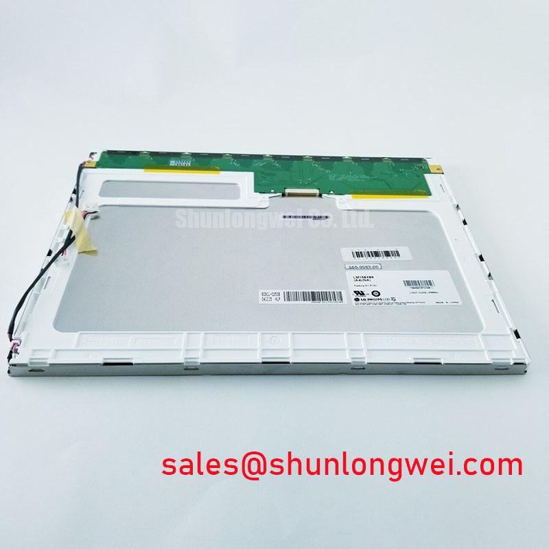
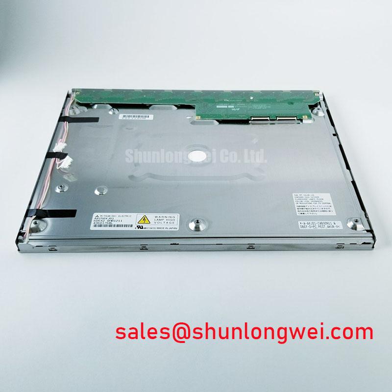
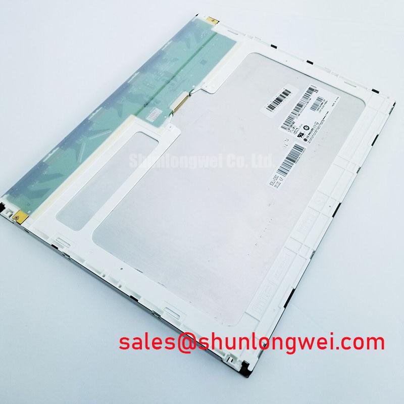
Start the service inspection by recording the label on the display assembly, checking the connector condition, and comparing the part number with the failed unit before applying power. The exact identifier is LM150X08-TLA1, manufactured by LG Display. The supplied factory specification identifies it as an Industrial Grade LCD/HMI Panel in a TFT LCD Display Module format, with an official factory specification status.
This information establishes the product identity, but it does not by itself confirm every system interface or operating limit required by a particular console. A replacement evaluation should therefore begin with the original panel documentation, the equipment service manual, and the installed cable assembly. The system integrator should verify the required supply voltage, signal format, backlight architecture, connector pinout, mechanical envelope, and temperature limits from those original documents.
| Model | LM150X08-TLA1 |
| Manufacturer | LG Display |
| Product category | Industrial Grade LCD/HMI Panel |
| Assembly format | TFT LCD Display Module |
| Specification status | Official Factory Spec Verified |
For a black screen, separate the fault domain before removing the panel. Confirm that the host controller starts correctly, inspect the display supply at the panel connector, and check whether the backlight responds independently from the image signal. A dark display can result from a missing supply rail, a disabled backlight command, a damaged cable, an absent video stream, or a panel fault. These conditions can look similar at the operator interface, so a known good signal path and controlled measurements are more useful than a single resistance reading.
Cold resistance checks should be performed only with the equipment fully isolated and the panel disconnected from active circuitry. Compare equivalent signal pairs and supply paths with the known good assembly where available. A resistance measurement alone cannot validate a high speed display interface, and it should not be used to apply external voltage to an unknown pin. The connector keying, pin numbering, and cable orientation should be recorded before reconnection.
Field Alert: Disconnect power before inserting or removing the display cable, because an energized connector can expose signal pins to an avoidable electrical transient.
Connector Assignment and Differential LVDS Timing, Pixel Clock, and Skew Compensation
Do not assume that a 20 pin or 30 pin connector has the same assignment across different LCD families. For LM150X08 TLA1 replacement work, the original panel documentation must confirm the connector count, pin sequence, supply pins, enable signals, clock pair, data pairs, and return paths. A mechanically compatible plug does not prove electrical compatibility.
When the interface is identified as differential LVDS by the equipment documentation, the troubleshooting sequence should begin at the transmitter and proceed toward the panel. Use the oscilloscope to compare the differential clock and data activity with a known good display path. Observe whether the clock is present during the expected display enable interval and whether the data pairs remain consistent with the active image. A missing clock, unstable enable signal, incorrect mapping, or excessive timing skew can produce a blank image, shifted content, split screen, incorrect colors, or intermittent operation.
The supplied product information does not provide a confirmed logic supply voltage or timing table for this model. The system integrator should verify whether the host equipment requires a specific logic rail from the original panel documentation. Do not select between possible supply values based on connector appearance or on the voltage used by another display. Power sequencing should also be checked against the source equipment documentation, including supply rise behavior, display enable timing, and any reset interval required by the controller.
Signal routing is a system design matter. As a Design Consideration, maintain the differential pair geometry, return path, and characteristic impedance required by the transmitter and receiver interface. The commonly used 100 ohm differential target may be relevant to an LVDS board design, but it must be treated as a routing requirement to verify against the actual host interface and stackup. Cable substitutions should preserve pair assignment and termination behavior rather than relying only on matching length or connector shape.
JEIDA and VESA mapping are not interchangeable assumptions. If the panel and controller use different color bit ordering, the result may appear as abnormal colors, image fragmentation, or a stable but unusable picture. Confirm the mapping in the original panel and controller documentation before changing firmware, cable wiring, or serializer settings. Where timing margins are uncertain, compare the suspect assembly with a known good unit under the same image pattern and temperature condition.
Low temperature operation can increase liquid crystal response time and make gray to gray transitions appear slower. This is a general LCD behavior and is not an LM150X08-TLA1 factory performance claim. For equipment expected to operate in cold locations, designers should verify the complete panel temperature specification, enclosure heat transfer, startup behavior, and any heater control already present in the equipment. The correct test is a controlled thermal evaluation using the actual image content and refresh timing, followed by verification that the display recovers without artifacts.
Optical Mode, Grayscale Inversion, and Viewing Direction Alignment
The installed optical mode must be confirmed from the original documentation before a viewing angle or grayscale diagnosis is made. The supplied factory record identifies the assembly as a TFT LCD Display Module, but it does not confirm TN, IPS, or MVA construction, nor does it provide a viewing cone, contrast curve, or grayscale inversion specification. Those values should not be transferred from a visually similar panel.
If the source documentation identifies a normally white TN panel, check the image from the intended operator position rather than judging the screen from an arbitrary side angle. TN displays can show viewing direction dependence, gray level shifts, or inversion patterns when viewed outside their intended axis. This may be particularly noticeable on radar graphics, dark backgrounds, thin text, and low contrast status indicators. The practical check is to display several neutral gray patterns and compare them at the actual mounting angle used by the equipment.
Anti glare treatment also affects field readability. Surface reflections, protective windows, contamination, and incorrect viewing direction can make a good panel appear dim or uneven in strong ambient light. For a marine radar or navigation bridge console, the display should be assessed with the final cover, bezel, lighting, and operator position in place. Salt residue and cleaning damage should be treated as enclosure and maintenance issues rather than attributed to the LCD module without evidence.
When the equipment uses TTL or LVDS transmission, verify clock stability, data hold behavior, and enable timing at the controller output and panel input. The correct limits depend on the actual transmitter, receiver, cable, and panel specification. If the image changes when the harness is gently repositioned, inspect connector retention, contact alignment, cable strain, and ground continuity before adjusting signal timing. Any timing change should be validated against a stable test image over the intended operating temperature window.
For replacement assessment, compare the optical result with the removed unit while both are driven by the same controller and image source where practical. Record the operator viewing position, ambient illumination, cover glass condition, and brightness setting. This avoids treating an enclosure reflection or viewing angle mismatch as a panel electronic failure.
Backlight Integration, Dark Field Uniformity, and Light Guide Stress
The factory data supplied for LM150X08-TLA1 does not confirm the backlight type, driver topology, LED current, PWM input, dimming range, light guide construction, or rated service life. These items require verification from the original panel datasheet or equipment schematic. In particular, a general claim about a 50,000 hour MTBF or brightness depreciation must not be assigned to this model without an authoritative source defining the test conditions, failure criterion, temperature, drive current, and maintenance assumptions.
Begin a backlight diagnosis by separating illumination from image generation. If the display produces a faint image when viewed under controlled external light, the video path may be active while the backlight circuit requires investigation. If no image is present, check the supply, enable command, signal path, and panel response as separate branches. A backlight fault can involve the driver, cable, protection circuit, light source, or system control signal, so the measured voltage and current should be compared with the original design documentation.
For an LED backlight system confirmed by the equipment documentation, the driver should be checked for its open load and short circuit response. An open LED string may cause the driver to raise its output until protection intervenes, while a short or abnormal load may trigger current limiting or shutdown. These are general driver behaviors, not confirmed internal features of LM150X08-TLA1. Diagnostic output, fault latch behavior, restart timing, and allowable load conditions must be verified at the driver board level.
PWM dimming should also be treated as a system parameter. The supplied information does not confirm a 200 Hz to 1 kHz operating range for this panel. If the host system uses PWM, designers should verify the accepted input format, frequency, duty cycle response, polarity, and minimum pulse behavior from the source documentation. The evaluation should include camera observation, operator viewing, and oscilloscope checks at the driver input. Audible noise or visible flicker can originate in the driver, mechanical vibration, camera aliasing, or an incompatible control waveform.
Dark field mura or localized brightness variation should be inspected with a uniform black and gray image after the panel has been installed in its final chassis. Uneven pressure from the bezel, cable routing, clips, or fasteners can change the optical appearance. The supplied factory parameters do not specify an LM150X08-TLA1 chassis tolerance or an approved fastener torque. Any mounting torque must therefore come from the equipment mechanical drawing or the panel manufacturer’s installation documentation. Tightening hardware by feel can distort the assembly and complicate later diagnosis.
For a marine console evaluation, the display should be tested with the intended sealing arrangement and protective window. The environmental design must address moisture, salt contamination, condensation, and thermal expansion at the enclosure level. Engineers may consult Industrial Display and HMI Solutions as a reference point when reviewing maintenance access, environmental protection, and display integration conditions.
Thermal Cycling, Polarizer Adhesives, and Perimeter Seal Integrity
Thermal cycling tests should begin with a visual inspection of the polarizer surface, bezel interface, cable exit, and perimeter sealing features. The available factory record does not state a confirmed operating range, storage range, adhesive construction, epoxy formulation, or gasket qualification for LM150X08-TLA1. Do not infer a temperature rating from the industrial category alone. The complete rating must be taken from the original manufacturer documentation for the exact revision.
At sub zero temperatures, liquid crystal viscosity can increase and gray to gray transitions can become slower. This general behavior may affect moving radar returns, scrolling text, and rapidly changing alarm graphics. A heater strip, if present in the host equipment, should be evaluated as part of the system rather than assumed to be a panel feature. Verify heater control, warmup logic, sensor placement, condensation management, and image usability during startup. The final acceptance condition should be defined by the equipment designer and measured with representative screen content.
Thermal expansion differences between the display assembly, chassis, protective window, cable, and sealing materials can create mechanical stress during repeated temperature changes. As a Design Consideration, allow the enclosure and mounting method to accommodate the documented expansion behavior of the complete assembly while maintaining retention and environmental protection. The appropriate clearance, gasket compression, and fastener arrangement are system determined and should be validated through the equipment qualification plan.
After thermal exposure, inspect for edge discoloration, bubbles, delamination, surface marks, intermittent lines, connector movement, and changes in backlight uniformity. An image defect that appears only after heating or cooling should be correlated with supply voltage, signal integrity, mechanical pressure, and recovery time. Avoid assigning a single cause until the defect has been reproduced under controlled conditions and compared with the known good signal and mechanical path.
For harsh outdoor equipment, sealing integrity belongs to the finished console. A display module alone does not establish a system IP rating, salt fog qualification, EMC compliance, or marine equipment certification. The equipment manufacturer or system integrator must verify those requirements for the complete assembly, including the panel, controller, cable, bezel, protective window, power supply, and enclosure.