Content last revised on October 9, 2026
Thermal Cycling Degradation of Polarizer Adhesives and Sealant Gasket Integrity
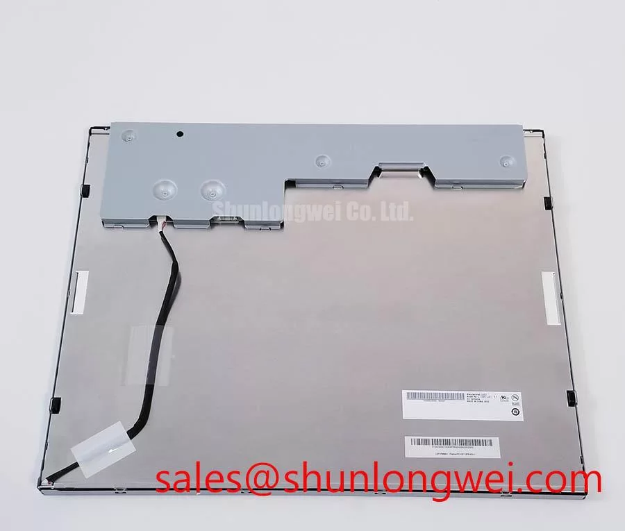
Check the incoming panel under controlled lighting before installation: inspect the TFT-LCD surface, bezel, connector area, and flexible cable for visible damage, then compare the replacement label with the equipment documentation. For the P370IVN02-0, the supplied factory information identifies an AUO Industrial Grade LCD/HMI Panel in a TFT-LCD Display Module package. The available factory specification context does not provide a verified resolution, active area, luminance, interface pinout, supply voltage, backlight type, viewing angle, or operating temperature range, so those values should be confirmed from the original panel documentation before electrical connection.
| Parameter | Factory specification status |
|---|---|
| Model | P370IVN02-0 |
| Manufacturer | AUO |
| Product category | Industrial Grade LCD/HMI Panel |
| Package or enclosure | TFT-LCD Display Module |
| Specification status | Manufacturer and model/category identified; detailed specifications require confirmation |
| Resolution, interface, voltage, backlight, dimensions, and temperature rating | Verify against the original panel documentation before integration |
This information makes the part suitable for controlled replacement assessment in industrial displays, HMI assemblies, monitoring terminals, and similar equipment where the mechanical and electrical interface is already defined by the host system. It should not be treated as proof of compatibility with every display controller. The system integrator should verify the required supply voltage, signal interface, backlight drive arrangement, timing configuration, and connector orientation from the original panel documentation.
For engineers evaluating a replacement in a high-voltage substation protection or SCADA dispatch console, the first practical comparison is mechanical interchangeability. Confirm the mounting points, bezel opening, panel thickness, cable exit direction, connector position, and clearance around the display assembly. A matching model number alone does not establish that the host controller, backlight circuit, and cable assembly are electrically compatible.
💡 Bench Tip: Use ESD protection during inspection and keep the display cable fully aligned and evenly seated before locking the connector; never force a connector that does not enter smoothly.
For incoming quality inspection, expose the display assembly only to the environmental limits stated in the original AUO documentation or the equipment qualification plan. The supplied information for P370IVN02-0 does not confirm a rated operating range of minus 30 degrees Celsius to plus 85 degrees Celsius, so those values must not be presented as this model’s factory rating. They may be used only as example conditions for a separate system-level qualification when the equipment specification requires them.
At low temperature, liquid crystal response can become slower, which may be visible as delayed gray transitions, image smearing, or a temporary change in motion clarity. These observations are screening results, not proof of a specific internal failure. A useful test compares the cold-start image with a known-good panel using the same controller, signal timing, brightness setting, and test pattern. Record the time required for stable image reproduction, then repeat the comparison after the panel returns to the laboratory reference condition.
Perimeter seal integrity should be assessed through visual inspection of the bezel and exposed display edges. Look for lifting, contamination, edge separation, deformation, or signs of moisture entry. Do not infer the construction material or adhesive chemistry unless it is stated in the manufacturer’s documentation. If the panel will be installed behind a sealed industrial enclosure, the complete assembly requires its own thermal cycling, condensation, vibration, and ingress evaluation.
Outdoor or high-illumination service requires a separate optical check. The supplied factory data does not verify a contrast ratio above 500:1 at 50,000 lux, nor does it confirm a particular anti-glare coating. Engineers should therefore test readability under the intended ambient light, inspect black-level stability, and confirm that the selected cover window does not introduce excessive reflections. A camera-based measurement system or calibrated photometer can support comparison between the removed panel and the replacement, but the result should be recorded as application test data rather than an AUO factory specification.
When the display is considered for a high-voltage substation protection or SCADA dispatch console, the enclosure, heater, ventilation path, and front-window design can influence the panel environment. Designers should verify warm-up behavior, condensation control, and optical readability at the actual installation location. Broader system guidance is available through Industrial Display and HMI Solutions, while the specific panel limits remain subject to the original product documentation.
Backlight Driving, PWM Dimming, and Flicker Assessment
The supplied factory information identifies the unit as a TFT-LCD display module but does not confirm whether this exact configuration uses an LED backlight, a CCFL assembly, an integrated driver, or a separately controlled backlight interface. The system integrator should verify the backlight technology and required drive method from the original panel label, controller board, and documentation before applying power. Do not connect a generic constant-current source or a legacy high-voltage backlight supply solely because another panel has the same physical size.
For a replacement inspection, begin with the host system’s existing backlight circuit. Check connector keying, pin assignment, enable logic, dimming input, and current-control arrangement against the known-good assembly. The panel should be powered through an appropriate current-limited laboratory setup during bench evaluation. If the original system uses pulse-width modulation, observe the control signal with an oscilloscope and compare the waveform with the service documentation. A visible flicker assessment should be performed at several brightness settings and with a camera or photodiode method when the application involves long viewing periods.
A PWM range of 200 Hz to 1 kHz, a 1000:1 dimming ratio, and a backlight half-life above 50,000 hours are not verified factory parameters in the supplied data for P370IVN02-0. They should therefore be treated as system requirements or qualification targets only when specified by the equipment designer. Frequency selection, duty-cycle behavior, acoustic performance, and thermal loading depend on the actual backlight driver and enclosure. The engineer responsible for the display controller should validate these characteristics at the required luminance range.
Backlight uniformity should be checked using a full-white test image after the display has reached a stable condition. Inspect the center, corners, and edge regions for luminance variation, color shift, dark areas, or localized haze. A full-black image is useful for checking unwanted glow and uneven illumination, while gray patterns can reveal drive instability that is not obvious on white. These observations should be compared with the removed unit or an approved reference panel under identical camera exposure and viewing geometry.
Acoustic noise should also be checked when the display assembly is installed near an operator desk or control-room console. Any audible behavior may originate from the driver, converter, enclosure, or mounting structure rather than the LCD cell itself. If the original documentation specifies a backlight driver, retain its electrical arrangement unless the system designer has completed a replacement qualification. The panel model should not be treated as an independent guarantee of flicker performance, luminous lifetime, or complete display-system reliability.
Industrial EMI Noise Immunity, Chassis Shielding Continuity, and Common-Mode Filtering
Before investigating image noise, verify the signal path from the controller to the display. Inspect the cable seating, connector latch, cable bend radius, shield termination, chassis bonding, and separation from switching power wiring. Horizontal bands, intermittent pixels, or image jitter can have several possible sources, including timing mismatch, connector contact variation, grounding arrangement, cable coupling, or controller instability. A symptom should not be assigned to the panel without comparison against a known-good cable and display path.
The supplied factory information does not define the LVDS pinout, FFC assignment, shielding construction, electromagnetic immunity level, or EMC certification status of this model. Confirm every signal and power connection using the original panel documentation. Do not assume that a mechanically similar connector has the same pin order. During bench testing, use an oscilloscope to compare the suspected signal with the known-good path, paying attention to signal quality during backlight switching and when nearby motors or converters change operating state.
Shield continuity is an integration consideration rather than a confirmed product specification. Where the equipment design uses a shielded cable, maintain the intended termination method and avoid adding long unreferenced shield pigtails without system-level validation. Common-mode ferrite components may be evaluated by the system designer when conducted or radiated noise is present, but their value, impedance curve, location, and effect on signal edges must be selected from measured results. The LCD module itself should not be described as independently passing an entire equipment EMC standard.
High-voltage substation protection and SCADA equipment can include relays, variable-frequency drives, switching supplies, and long cable runs. These surrounding circuits can affect display behavior even when the panel is operating within its own electrical limits. Test the display with the actual controller, enclosure, cable routing, and grounding arrangement whenever possible. A temporary laboratory connection may hide a noise path that appears after installation, while excessive filtering may reduce signal margin or alter the controller interface.
Low-temperature testing should separate display response effects from communication integrity. If image transitions slow in a cold chamber, record the panel temperature, controller condition, image pattern, and timing behavior. If the image breaks up or loses synchronization, inspect the cable and interface waveform before attributing the result to liquid crystal response. Any heater strip, temperature controller, or enclosure thermal device belongs to the system design and requires independent safety and compatibility testing.
Chassis Fastener Loading and Optical Mura Inspection
Mechanical installation should begin with a dimensional comparison against the removed display. Confirm the outer bezel envelope, mounting-hole pattern, connector clearance, cable path, and contact surfaces before tightening any fastener. The supplied factory parameters do not specify an approved chassis torque for P370IVN02-0. A value of 0.35 to 0.45 N·m for an M3 fastener is therefore not an AUO factory specification for this model and should not be applied without confirmation from the equipment manufacturer or mechanical drawing.
Uneven frame loading can produce pressure marks, brightness variation, or localized mura, but these effects depend on the actual bezel design, support points, fastener geometry, gasket arrangement, and panel construction. Install the display without twisting the frame, keep the mounting surfaces clean, and tighten in a controlled cross-pattern only when the host equipment procedure requires it. The final torque must be determined by the system mechanical design and verified with an optical inspection after assembly.
Use full-white, mid-gray, and black test patterns to inspect the display after mounting. Compare the unfastened bench condition with the installed condition at the same brightness and camera exposure. A new dark region or bright patch after fastening may indicate mechanical stress, an uneven support surface, cable interference, or a display assembly issue; it does not establish one specific cause. Looseness and excessive loading should both be investigated through controlled mechanical checks rather than repeated tightening.
For a SCADA dispatch console, the front bezel, protective window, gasket, and service door can change the optical result seen by the operator. Verify that the window does not press against the active display area and that the cable is not trapped between the module and chassis. Recheck image uniformity after vibration or thermal testing if those tests form part of the equipment qualification plan. Record the inspection conditions and compare the results with the approved reference unit.
The P370IVN02-0 should be integrated only after the host system documentation confirms its electrical interface and mechanical fit. The available factory data establishes the AUO manufacturer, TFT-LCD Display Module type, and Industrial Grade LCD/HMI Panel category; additional values require document-based verification or application testing.