


Content last revised on September 10, 2026
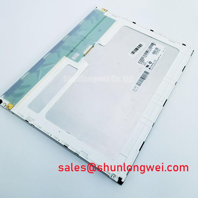
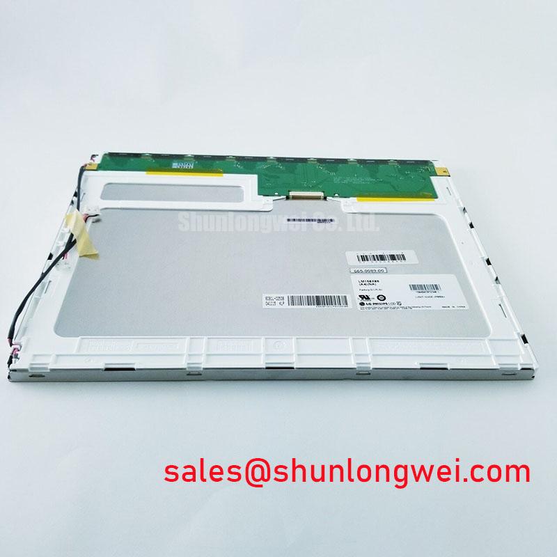
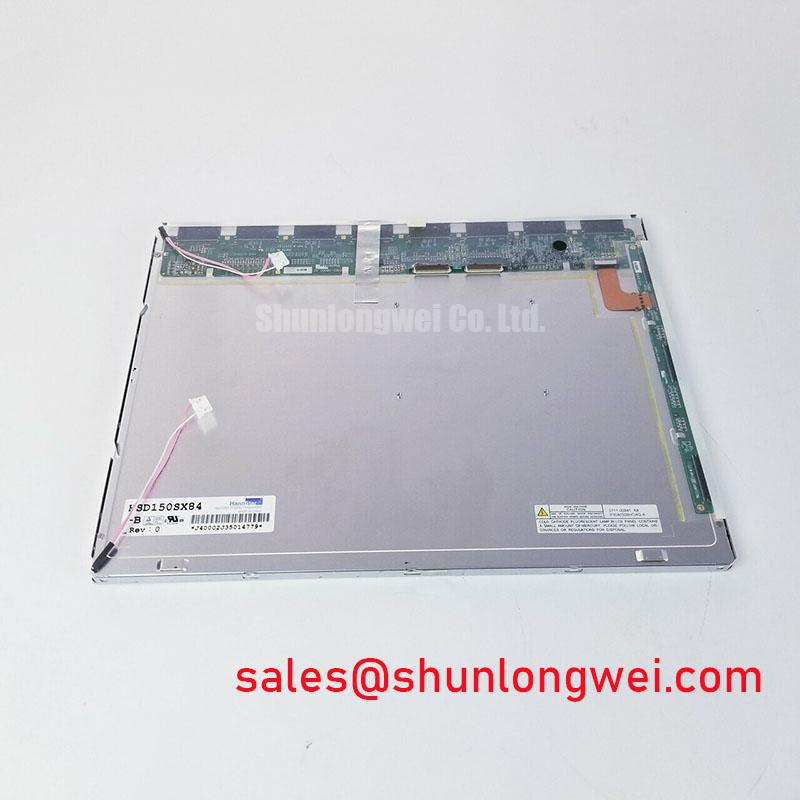
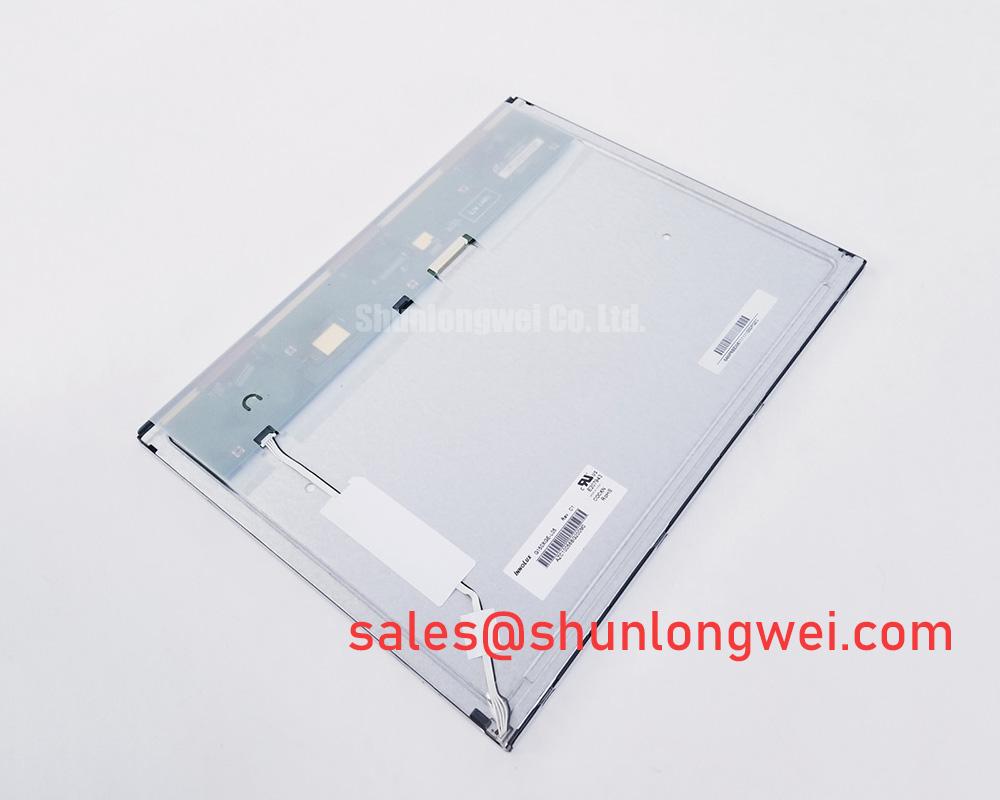
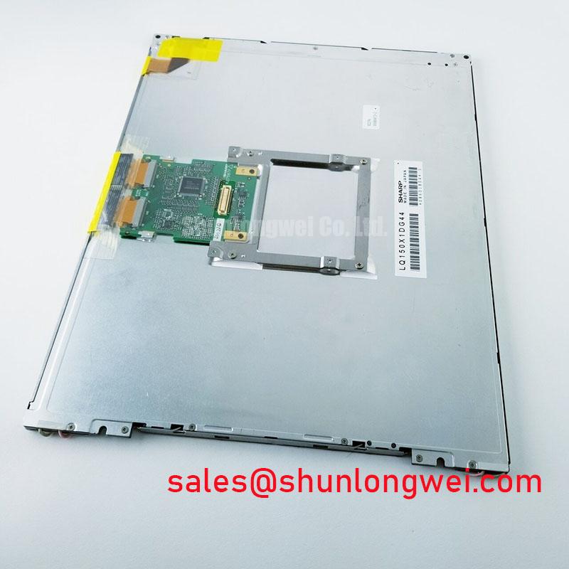
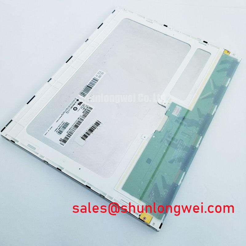
LM150X08-TLB1 LG Display Industrial Grade TFT LCD Module
With power removed, first confirm the panel label reads LM150X08-TLB1, inspect the TFT LCD module frame and connector area for distortion or contamination, then compare the original machine documentation before applying panel or backlight power. This is an Industrial Grade LCD/HMI Panel manufactured by LG Display and supplied as a TFT LCD Display Module.
The available factory information identifies the product category, manufacturer, module construction, and verified specification status. It does not establish the electrical input rail, connector pin assignment, signal interface, optical performance, backlight construction, environmental ratings, viewing geometry, or regulatory approval. For a repair or replacement assessment, the system integrator should verify those requirements from the original panel documentation and the host equipment circuit before installation.
| Item | Official Specification |
|---|---|
| Product model | LM150X08-TLB1 |
| Manufacturer | LG Display |
| Product category | Industrial Grade LCD/HMI Panel |
| Module construction | TFT LCD Display Module |
| Specification status | Official Factory Spec Verified |
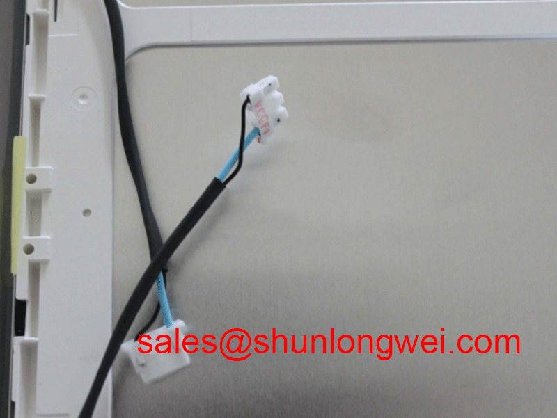
In equipment such as CNC operator panels and robot teach pendants, a black screen can originate at several points in the display chain: incoming supply, display interface cable, timing controller path, backlight driver, controller board, or the LCD module itself. Start with the machine wiring diagram and a known safe measurement procedure. Check that the display cable is fully seated at both ends, examine cable strain points, and compare power and signal behavior with the original equipment requirements rather than applying generic panel assumptions.
⚠️ Field Alert: Disconnect system power and allow stored energy to discharge before connecting or removing the display interface cable, because live connector movement can expose signal pins to unintended voltage levels.
Radiated Emissions Compliance (CISPR Class A/B) via Backplate Multi-Point Star Grounding
Near a variable frequency motor drive, horizontal bands, intermittent pixel noise, touch interface instability, or image jitter can be associated with conducted or radiated interference, but none of these observations independently proves an EMC cause. The LM150X08-TLB1 is a display module, and its available official information does not declare independent CISPR Class A or Class B compliance. EMC conformity belongs to the completed equipment, including the panel enclosure, cable routing, controller, power supply, grounding structure, and connected motor system.
As a Design Consideration, service personnel should inspect whether the original enclosure uses a conductive backplate, bonding points, cable shield terminations, and separation between display wiring and high energy motor conductors. A shielded display cable can only provide its intended common mode noise control when its termination method follows the original equipment design. If the system uses a shielded FFC or LVDS style cable, confirm the actual connector arrangement and shielding method from the host documentation. Do not assume that this panel uses a particular interface solely from the panel family name.
Multi point bonding of an enclosure backplate can be evaluated where the equipment architecture calls for it, particularly when cable shields and conductive enclosure sections must share a controlled return path. The purpose is to limit unwanted common mode coupling into low level display signals. The system engineer should validate this with installed equipment measurements, observing the screen while the relevant drive and load conditions are operating. A temporary ferrite trial may help isolate a suspected cable borne interference path, but ferrite material, placement, and impedance must be selected and verified for the actual system spectrum.
Do not attribute a dim display to normal backlight ageing without confirming panel supply, brightness control behavior, cable integrity, and the host backlight driver. No official lifetime or brightness decay curve is provided in the verified information for this listing. A claim such as a fixed operating hour life or a specified time to half brightness would require the corresponding LG Display factory documentation. For broader enclosure, cable, and display integration practices, review Industrial Display & HMI Solutions.
Suppressing Localized Thermal Gradients to Prevent Chronic Optical Yellowing (Color Shift)
Inspect the panel perimeter, mounting rails, enclosure contact surfaces, and nearby power components before replacing a display that shows uneven brightness or localized color change. A visible optical change can be linked to heat concentration, illumination path variation, mechanical stress, contamination, signal processing, or panel ageing. It should be treated as an investigation result, not as proof of one material level failure mechanism.
As a Design Consideration, a metal support structure may be used by the host equipment to distribute heat away from narrow display edges when the original mechanical design provides such a path. The rail geometry, thermal interface method, fastening sequence, and allowable contact pressure are system determined. A replacement panel must sit flat in the original mounting position. Uneven clamping, a bowed enclosure, or contact with protruding hardware can create local mechanical loading that affects the visible surface or the display stack.
The factory information available for LM150X08-TLB1 does not identify the optical films, light guide material, backlight type, thermal rating, L70 value, B50 value, or the presence of an aluminium heat spreading feature. These attributes should not be inferred. If the equipment uses a separate brightness control signal, verify its electrical specification and waveform against the original controller documentation. Do not impose a generic PWM frequency or duty cycle range on a replacement panel without confirmation from the display and controller specifications.
A practical bench check begins with the panel operating in its original enclosure under normal equipment conditions. Observe whether the color or brightness change follows display warm up, backlight adjustment, a particular machine mode, or connector movement. Compare the image to a known good signal path when available. If the effect appears only under high ambient illumination, inspect the front window, protective overlay, and enclosure gasket for surface damage or contamination before assigning the issue to the LCD module.
Optical bonding is also an enclosure level integration method rather than an attribute confirmed for this panel. When an equipment design uses a bonded cover assembly, the replacement decision should preserve the original optical stack, environmental seal, and mechanical clearances. The installer should verify whether the LCD module is separate from the cover glass or supplied as part of a defined display assembly.
Dynamic Contrast Ratio Stabilization & Liquid Crystal Birefringence Temperature Tracking
When text becomes difficult to read, first compare the incoming image source, brightness setting, and panel condition before adjusting controller parameters. The verified factory information identifies LM150X08-TLB1 as a TFT LCD display module, but it does not state panel mode, contrast ratio, viewing angle, anti glare treatment, response time, color performance, or gamma voltage requirements. It is therefore not appropriate to label this exact model as TN, IPS, MVA, or another optical mode without the original factory data.
Temperature can affect the visible behavior of liquid crystal displays, including apparent response and contrast, but the expected result depends on the actual panel technology and the complete assembly. A slow transition, grayscale trail, or changing contrast in cold conditions may warrant examination of the panel temperature, display controller, supply stability, and source image timing. The system engineer should compare the behavior against approved equipment operating conditions and an established known good unit where possible.
Timing controller circuits generate and manage the analog and digital drive conditions required by the panel. If the host board provides adjustable gamma or image controls, preserve the original calibration process. Changing gamma related settings to mask a signal or illumination defect can create a misleading improvement while leaving the root condition unresolved. If an external controller board is used, verify the expected signal format, clock behavior, connector orientation, and power sequencing from the machine documentation.
Differential display links are often designed around controlled impedance cable assemblies, but the available official information does not confirm that LM150X08-TLB1 uses LVDS, TTL, or a particular differential impedance. Engineers evaluating a replacement should retain the original cable type and routing wherever possible, then verify the actual interface requirement from the original panel documentation. A scope comparison with the known good signal path can help identify waveform degradation, timing instability, or connector related discontinuity without assigning a single cause from the screen symptom alone.
If a heater strip or enclosure heater is present in the equipment, treat it as a host system feature. Its control thresholds, placement, and thermal safety limits must be verified by the equipment designer or service documentation. The available panel data does not confirm an internal heater or a specified subzero operating range.
High Humidity Storage Margins (60°C / 90% RH) & Delamination Prevention Protocols
Before returning a repaired CNC operator panel or robot teach pendant to service, inspect the enclosure seal, connector area, display perimeter, and front surface for retained moisture, residue, or trapped debris. Humidity related display symptoms can overlap with cable corrosion, controller board contamination, enclosure leaks, front overlay damage, and supply instability. A visual inspection should be supported by the equipment service procedure rather than a single symptom based diagnosis.
The available verified factory details for LM150X08-TLB1 do not specify storage humidity, operating humidity, thermal cycle limits, perimeter seal construction, delamination resistance, or a temperature range extending from subzero conditions to elevated industrial temperatures. The stated heading describes an evaluation topic, not an official rating for this display module. Do not store or qualify this model at a stated humidity and temperature condition unless that condition is confirmed by the applicable LG Display documentation.
As a Design Consideration, keep removed display modules protected from condensation, direct contamination, and unnecessary handling of the active area and connector contacts. If equipment has been moved from a cold area into a warm humid workshop, allow the full assembly to reach a stable condition under the equipment maintenance procedure before energizing it. The required delay, environment, and inspection method are determined by the host system and its documented service controls.
Where a front cover, gasket, or bonded optical assembly is part of the machine, verify that its compression and sealing arrangement remain consistent after panel replacement. A panel that is electrically compatible may still be unsuitable if its mechanical outline, mounting features, connector position, front stack clearance, or enclosure interface does not match the original installation. The official information supplied here confirms the industrial TFT LCD module classification, not replacement interchangeability across other panel variants.
If brightness control is used after reassembly, check that the display remains readable and stable through the equipment’s intended operating modes. Any observed flicker, audible behavior, or brightness nonlinearity should be assessed against the original controller and backlight design. The required dimming method and its operating characteristics must be verified from the panel and host controller documentation.