


Content last revised on October 16, 2026
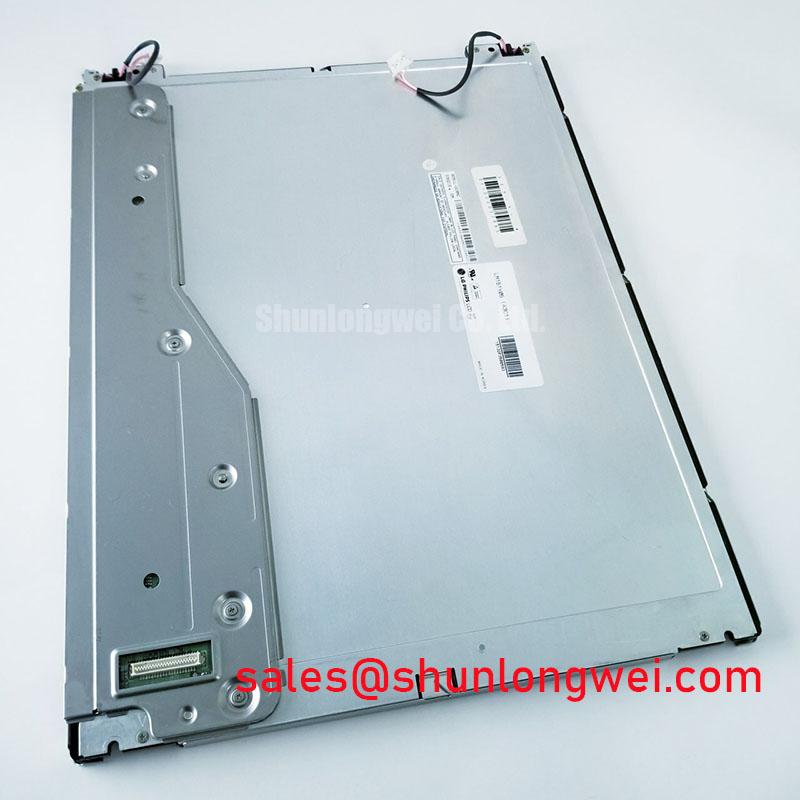
LM151X05-B3 Replacement Assessment
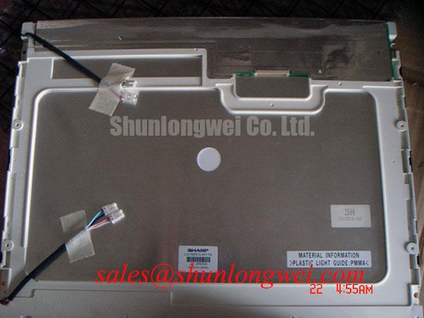
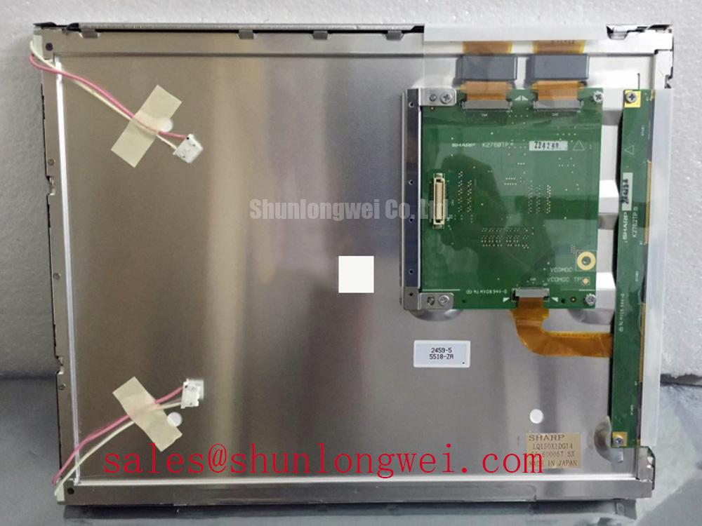
- Match the complete LM151X05-B3 designation on the panel label against the equipment service record before connecting a replacement.
- Inspect the display surface, mounting points, connector housing, and cable contacts for damage or contamination without applying pressure to the active area.
- Check the host connector pin assignment and supply requirements against the panel documentation before applying power.
- Prepare full-screen color patterns and a repeatable optical measurement position for checking pixel defects, brightness uniformity, and viewing behavior.
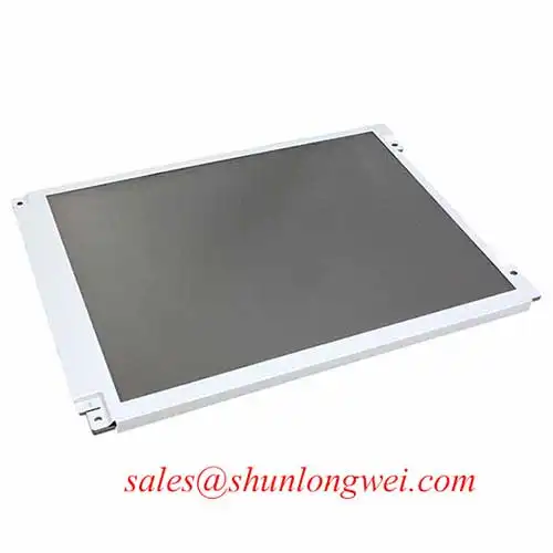
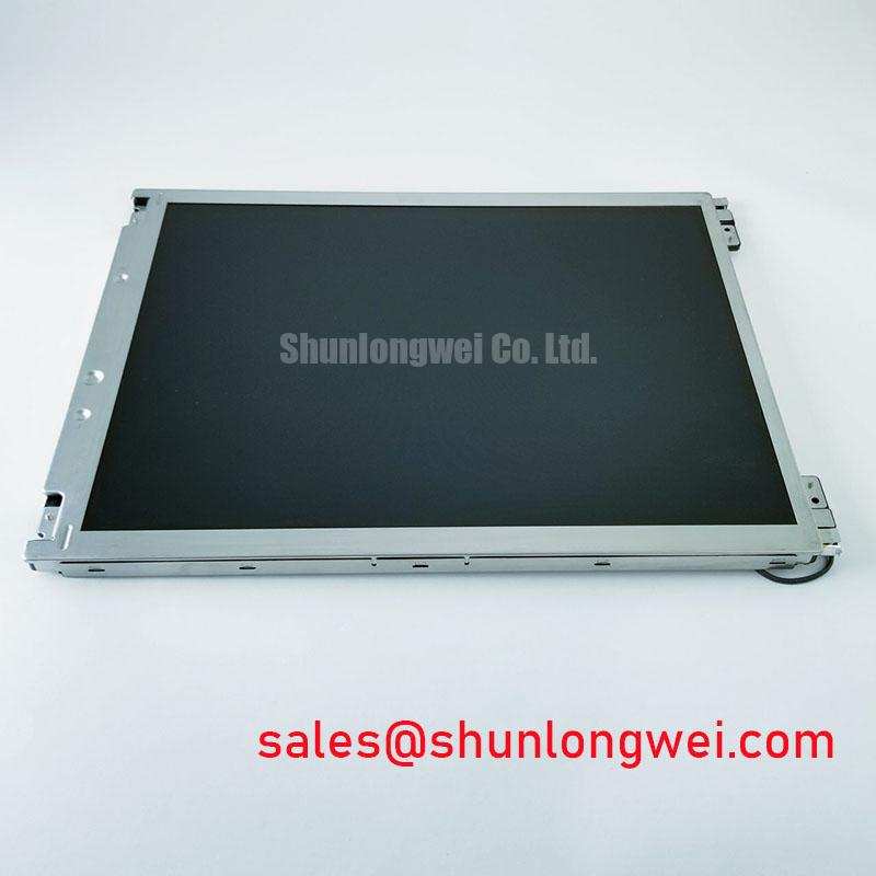
The LG Display LM151X05-B3 is a TFT-LCD active matrix color display module for evaluation in industrial LCD and HMI service work. Replacement assessment should connect three observations: whether the host drives the panel correctly, whether the image remains readable in the installed position, and whether the mechanical assembly fits without stressing the display.
| Product identity | Specification or verification requirement |
|---|---|
| Model | LM151X05-B3 |
| Manufacturer | LG Display |
| Module construction | TFT-LCD Active Matrix Color Display Module |
| Product category | LCD Display; industrial HMI integration assessment |
| Electrical, optical, and mechanical limits | Consult Datasheet for supply voltage, interface, resolution, dimensions, backlight requirements, temperature limits, and timing. |
Preventing Frame Lag & Image Smearing in Cryogenic Storage & Outdoor Industrial Facilities
Compare moving edges and grayscale transitions after the panel reaches a stable temperature, keeping the source pattern and host timing unchanged. As a Design Consideration, colder liquid crystal operation can slow optical transitions and increase visible trailing. A blurred transition therefore needs a different investigation from a missing frame, intermittent synchronization, or corrupted image data.
Separate optical response from host behavior by displaying both stationary fine detail and controlled motion. If stationary detail remains stable while moving boundaries trail, record the temperature and transition pattern. If stationary content also breaks up, examine the controller, cable, supply stability, and interface timing. Gray-to-gray behavior depends on the particular transitions being measured; a single moving pattern cannot establish every response characteristic.
For integration testing, evaluate transmitter clock quality and receiver setup and hold requirements using the documented interface. TTL timing and differential interface measurements require different probing methods. Select the method from the actual connector definition, then assess timing at the receiving end under the equipment’s intended environmental conditions. Cable substitution should preserve the required electrical and mechanical characteristics.
Environmental evaluation should also check connector seating, frame distortion, condensation exposure, and visible edge changes before and after conditioning. Treat these observations as assembly evidence rather than proof of a particular sealant composition. Cold storage and outdoor operation remain equipment qualification questions; this panel’s identity alone does not establish suitability for either environment.
Dynamic Contrast Ratio Stabilization & Liquid Crystal Birefringence Temperature Tracking
Measure white and black fields from the same position with ambient illumination controlled, then repeat the observation from the intended operator viewing direction. As a Design Consideration, liquid crystal birefringence and polarization behavior affect transmitted light, while reflected ambient light can reduce perceived contrast even when the electrical image remains stable.
Use a fixed backlight control setting when comparing temperature conditions. Automatic brightness adjustment and image processing can otherwise obscure whether the change originates in the panel, illumination system, or controller. Dynamic contrast claims should not replace measurements of static fields under stated conditions. Record grayscale separation, color shift, and dark-field uniformity alongside luminance.
The optical principles described in Liquid-Crystal Display (LCD) Polarizers and Optical Glass help explain why surface reflections and polarization affect readability. Inspect the assembled front surface under representative lighting: anti-glare treatment disperses reflections, whereas anti-reflection treatment addresses reflected light differently. Neither treatment should be assigned to the LM151X05-B3 without a corresponding product specification.
Evaluate off-axis grayscale directly rather than assuming a symmetric viewing cone or a particular liquid crystal mode. The general discussion of Viewing Angle Characteristics in LCDs provides context for this test. If a touch overlay is installed, assess its added reflections and verify glove and wet-surface response with the actual touch controller. Those responses belong to the integrated touch assembly.
Logic Supply Voltage Sequencing to Reduce Driver IC Latch-Up Risks
Capture the panel supply, interface activity, and backlight enable during startup and shutdown against the documented sequencing requirements. As an Engineering Recommendation, check for signal activity reaching an unpowered receiving circuit, unexpected supply interruptions, and delayed discharge before investigating intermittent startup artifacts. Supply amplitude, ramp behavior, and sequencing intervals must follow the actual panel and controller requirements.
Trace every connector position through the host schematic and cable drawing. Establish signal polarity, grounds, enable functions, and data assignments before evaluating an adapter. For a documented differential interface, preserve pair continuity and assess impedance discontinuities, skew, and common-mode disturbance against the transmitter and receiver limits. JEIDA or VESA mapping checks apply only where the documented interface uses those conventions.
In equipment containing switching drives, compare image stability with the interfering subsystem inactive and operating under representative loads. Correlate disturbances with cable routing, shield termination, grounding, and measured supply noise. This is a Design Consideration for the complete installation; panel operation does not independently establish equipment EMC compliance.
When comparing NL8048AC19-13 with the LM151X05-B3, assess each module’s dimensions, resolution, interface, optical behavior, and backlight connection independently. A product comparison does not establish interchangeability. Potential evaluation in a railway passenger information terminal or cab signalling display also requires equipment-specific checks for readability, environmental exposure, electrical compatibility, and applicable system requirements.
Single Vertical Hairline Defect & Sub-Pixel Column Driver Open-Circuit Localization
Display full-screen red, green, and blue patterns in sequence, recording whether a vertical line stays at the same physical column and which color fields reveal it. Follow with white, black, and grayscale patterns to distinguish a persistent column defect from content-dependent interference. A fixed line can justify further panel-path investigation, but it does not independently identify an internal open circuit.
💡 Bench Tip: Isolate power and use an ESD-controlled workstation before reseating the display cable, keeping the connector square while engaging its retention mechanism.
Retest after checking cable seating and the host image source. Avoid pressing the bezel or flexing the panel to provoke a change. For a dark display, oblique flashlight illumination can help reveal whether image modulation remains present beneath inadequate illumination. That observation supports separate checks of the backlight supply, enable control, connectors, and driver fault output, where provided.
Where the installed backlight driver provides open-circuit or short-circuit diagnostics, interpret its status using that driver’s documentation. Protection thresholds and recovery behavior belong to the specific driver circuit. Uneven brightness or color temperature also warrants a controlled spatial comparison rather than an immediate diagnosis of backlight failure.
For maintenance planning, distinguish brightness depreciation from failure statistics and retain the measurement conditions with each inspection record. The Ultimate Guide to Industrial TFT LCD Technology provides broader context for display selection and maintenance terminology. Record defect coordinates, test patterns, brightness settings, temperature, and photographs so subsequent inspections can compare the same conditions.