Content last revised on September 24, 2026
TTL 24-Bit Digital RGB Bus Synchronization & Logic Power Rail Verification
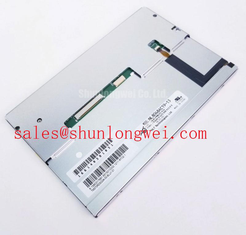
With the display disconnected from the equipment, begin by examining the connector area for uneven insertion marks, bent contacts, cracked locking features, or strain transferred from the cable bend. Then inspect the mating cable and controller output using the original service information. The verified factory information for NL8048AC19-13 does not state the required logic supply voltage, the digital interface format, the pin assignment, or the display timing. The system integrator should verify the required supply voltage from the original panel documentation before applying power.
The terms TTL, 24-bit RGB, JEIDA mapping, VESA mapping, and differential impedance describe interface conditions that can be relevant to industrial display systems, but they must not be assigned to this NEC module without its applicable documentation. A controller board may be designed for a parallel RGB interface, an LVDS interface, or another panel-specific arrangement. Connector appearance alone is not a sufficient basis for selecting an interface adapter or replacement cable.
During powered evaluation, use a known-good controller path where possible and observe the image from power application through stable operation. A blank white screen, split image, unstable color fields, intermittent vertical patterns, or shifting image regions can arise from several causes, including incorrect power sequencing, mismatched timing, incomplete connector engagement, cable damage, or controller configuration. These observations should be compared against a known-good signal path with appropriate test equipment rather than interpreted as a single definitive panel fault.
Power-on rise time requirements and logic rail sequencing must be taken from the relevant module documentation or the original equipment design records. A display controller can begin sending pixel data too early, retain a signal during power removal, or apply an incompatible voltage if the system sequence is altered during a repair. Design Consideration: keep display power, data enable, clock, and reset behavior under control of the host system sequence, then verify image stability during repeated start and shutdown tests.
Cold ambient evaluation also needs careful interpretation. Liquid-crystal response can become visibly slower at low temperature, producing delayed transitions or temporary image smearing during test patterns. That behavior should be assessed as a temperature-dependent optical response, not automatically as evidence of a failed panel. If the equipment uses an enclosure heater, its control method, sensor placement, and enable conditions are system-level functions that must be checked against the machine documentation.
Where a repair requires comparison with another display family, the NL128102BC28-04 can be reviewed as a separate NEC panel reference. It should not be treated as an automatic substitute for NL8048AC19-13; resolution, timing, connector location, electrical requirements, optical characteristics, and mounting geometry require direct verification before any compatibility decision.
💡 Bench Tip: Disconnect system power before handling the display cable, use ESD-controlled handling, and insert the flat cable squarely before closing its locking mechanism.
Flush-Mount Open-Frame Bezel Integration & Perimeter Gasket Shock Isolation
Mechanical inspection should start with the active viewing area, front bezel contact points, side edges, and rear support locations. Look for evidence that the original enclosure has concentrated force onto one edge of the TFT-LCD display module. Localized compression can appear as uneven brightness, dark areas, color variation, or pressure-related marks that become more visible on a uniform grey, white, or black test image. A full-screen solid-color pattern is useful because it reveals issues that can be missed when testing only a boot logo or text-based screen.
The official information available for NL8048AC19-13 does not define its outside dimensions, mounting-hole pattern, bezel depth, fastener type, gasket material, or approved tightening torque. These values must therefore be measured from the removed original panel and checked against the host assembly drawing. Do not infer mounting dimensions from the part-number format or from the size of a visually similar display.
Design Consideration: a flush-mounted panel should be supported by the intended frame surfaces rather than clamped through the visible area. If the host enclosure uses perimeter sealing or shock-isolation material, its thickness and compression behavior should be preserved as required by the equipment design. The aim is to distribute contact pressure around the designated support surfaces while avoiding twist, point loading, and cable strain.
Where an equipment drawing specifically calls for M3 hardware, a cross-pattern tightening process can help distribute load across the frame. Use only the torque specified for the enclosure, thread engagement, hardware grade, support frame, and original assembly requirements. The correct limit must be determined by the host equipment design rather than treated as an NEC factory torque specification for this model.
Vibration-prone equipment requires more than a tight bezel. The panel, mounting frame, cable route, and controller board must move within the intended mechanical constraints without transferring repeated bending force into the display connector. When evaluating a telematics display for heavy earthmoving equipment, engineers should treat shock isolation, enclosure sealing, retention features, and cable support as host-system compatibility items. The panel’s factory classification as industrial grade does not independently certify the complete installed assembly for a specific vibration, shock, ingress, or vehicle-duty standard.
Signal stability should also be checked across the expected operating environment. Controller clock quality, data hold behavior, cable routing, and grounding arrangement can influence image quality, particularly where the display is connected through long harnesses. If image instability appears after reassembly but not during bench testing, inspect frame contact, cable routing, connector stress, and the controller-to-panel signal path before assigning the issue to the LCD module.
Shielded FFC/FPC Flat Flexible Cable Grounding across 360-Degree Connector Shells
A flat-flex cable should be examined across its complete bend path, not only at its visible connector end. Repeated flexing near a hinge point, sharp chassis edge, cable tie, or unsupported transition can damage conductors or create intermittent contact behavior. Inspect for creases, exposed reinforcement material, lifted conductor ends, contamination on the contact fingers, and signs that the locking bar has been closed over a misaligned cable.
The factory information provided for NL8048AC19-13 does not confirm whether the module uses FFC, FPC, LVDS, TTL RGB, a shielded cable shell, or a particular grounding arrangement. Any replacement cable or interface board must match the original equipment documentation and physical connector definition. It is not appropriate to assume that a cable with the same contact count, pitch appearance, or connector location will have the same pinout or shielding requirement.
Design Consideration: where the host display harness includes a shield or connector shell intended for chassis bonding, preserve the original grounding architecture during service. Shield termination has to be evaluated with the enclosure, controller ground reference, cable construction, and nearby noise sources in mind. A 360-degree connector-shell termination is a common system-level technique in some shielded harness designs, but it is not a confirmed construction feature or NEC requirement for this particular module.
Variable-frequency motor drives and other high-energy switching equipment can create conducted and radiated disturbances that affect display signal paths. Horizontal noise bands, pixel jitter, intermittent image corruption, or touch-related display disturbances may indicate a system noise-coupling issue, but they can also be associated with data timing, supply ripple, cable damage, or controller malfunction. Verify the behavior with an oscilloscope and a known-good signal path while reviewing the cable route and grounding continuity.
Ferrite components, shielded harnesses, metal enclosure bonds, and controller filtering are system design choices. Engineering Recommendation: evaluate any suppression measure in the installed equipment because a change that improves one cable path can alter common-mode behavior elsewhere. The final arrangement should be tested against the equipment’s operating conditions rather than selected solely from generic display repair practice.
For technicians investigating image noise, inspect whether the cable has been routed beside motor leads, relay coils, high-current conductors, or switching power hardware. Restore original separation, shield contact, and strain relief where service documentation identifies them. Avoid folding excess cable into a tight stack behind the panel, as this can add mechanical stress and complicate later fault isolation.
Suppressing Localized Thermal Gradients to Prevent Chronic Optical Yellowing (Color Shift)
Run a controlled visual check using uniform white, grey, red, green, blue, and black patterns after the display has reached a stable operating condition. Compare the center, corners, and narrow edge regions for brightness variation, color shift, flicker, pressure marks, and localized dim areas. This approach helps distinguish visible optical non-uniformity from interface artifacts that only appear with changing image content.
The available official specification for NL8048AC19-13 does not identify the backlight technology, color temperature, luminance, optical bonding construction, LED service life, L70 value, B50 value, thermal limit, or allowable operating temperature. No backlight lifetime figure or optical-yellowing mechanism should be assigned to this module without the applicable NEC documentation. The system integrator should verify the relevant environmental and backlight requirements from the original panel documentation.
Design Consideration: avoid creating local heat concentration along display edges or behind the rear housing. Heat from controller boards, power converters, enclosure solar loading, or adjacent equipment can create uneven conditions across the assembled display. Where the host design uses heat-spreader rails, conductive brackets, airflow paths, or thermal barriers, retain their original placement and contact condition. Their suitability is determined by the equipment thermal design and must be validated during installed testing.
Optical bonding, if present in an existing display assembly, should be assessed as an assembly characteristic rather than presumed from the TFT-LCD module category. A bonded cover lens can affect reflection control, contamination resistance, impact behavior, and repair method, while an unbonded stack may require different gasket and support treatment. Check the removed unit and the equipment drawing before separating any front-layer construction or transferring a panel into another frame.
For HMI screens that remain on a static status page for extended periods, the practical test is to display neutral patterns before and after the operating screen and record whether any retained image is visible. Temporary image persistence, uneven backlight appearance, controller-generated artifacts, and software rendering behavior can resemble one another. Evaluate the display module together with the controller output and screen content before reaching a repair decision.
Useful inspection methods for industrial TFT-LCD service, optical evaluation, cable handling, and interface selection are also discussed in The Ultimate Guide to Industrial TFT LCD Technology. For NL8048AC19-13, final integration remains dependent on verified original documentation, host mechanics, approved electrical sequencing, and installed image testing.