

Content last revised on October 12, 2026
Suppressing Pixel Jitter & Horizontal White Lines Induced by Adjacent 400V Motor Drives
Display full-screen white, black, and primary-color patterns on the NL8048AC19-14F before closing the equipment enclosure, and record whether visible defects remain fixed to the glass or change with cable position, image content, or machine activity. Keep the controller settings and illumination conditions unchanged between checks so that panel behavior can be separated from signal-path and backlight-driver effects.
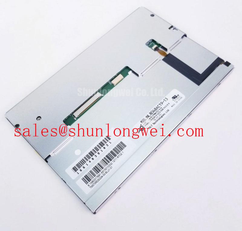
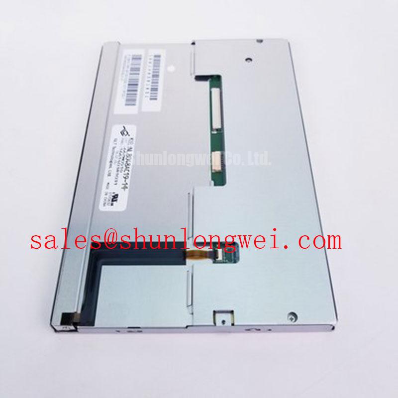
The NEC NL8048AC19-14F is an active matrix color TFT-LCD module in the industrial LCD/HMI panel category. Its supplied specification status is Decoded Baseline / Standard Form Factor; that designation does not establish electrical interchangeability. Incoming inspection should associate the complete model suffix with the equipment drawing, connector arrangement, and approved display configuration rather than treating a shared family designation as replacement approval.
Correlate pixel jitter and horizontal bands with switching activity in an adjacent 400 V motor-drive installation, treating that voltage as an equipment context rather than a panel rating. As a Design Consideration, compare the display with the drive inactive and active while holding image content constant. A repeatable correlation supports investigation of coupled interference, but does not distinguish cable pickup from supply disturbance or controller timing faults.
As an Engineering Recommendation, examine the installed display cable against its actual interface drawing before changing grounding. For an interface documented as LVDS, evaluate differential signal integrity and common-mode disturbance separately. Where the cable assembly incorporates shielding, inspect continuity through the connector and chassis termination. Circumferential shield contact can be evaluated where the connector supports it; attaching an improvised ground to an exposed flexible cable can instead alter the intended return path.
Common-mode ferrite suppression is a Design Consideration for a demonstrated interference path, not an accessory requirement for the NL8048AC19-14F. Its placement and impedance characteristics should follow measured disturbance behavior and subsequent signal-integrity checks. Separate display wiring from motor conductors where the enclosure permits, then repeat the original image test to determine whether the change improves stability without introducing another fault.
Inspect flexible-cable routing for creases, connector-side tension, and movement concentrated at the contact transition. As an Engineering Recommendation, provide strain relief outside the connector engagement area and evaluate movement through the equipment’s actual service travel. Connector locking and cable support deserve separate checks: a closed latch does not establish that every contact is seated, and a supported cable should not pull sideways on the receptacle.
💡 Bench Tip: With power isolated and ESD controls in place, seat the display cable squarely before engaging its connector lock.
Trace the complete chain from controller output through the cable to the panel, with the backlight power path assessed separately. The related NL8048AC19-13 provides another display reference when comparing system configurations, not a presumed companion driver or interchangeable module. Cable mapping, controller configuration, and illumination control remain distinct compatibility checks.
Mitigating Gray-to-Gray (GTG) Response Time Escalation during Cold-Start Machine Power-Up
Capture the same moving grayscale pattern during an approved cold start and after thermal stabilization. As a Design Consideration, lower liquid-crystal temperature can slow optical transitions, making motion trails more apparent even when the incoming image timing remains stable. Compare those optical changes with supply and enable waveforms so that response lag is not confused with a startup sequencing fault.
For NL8048AC19-14F integration, the Engineering Recommendation is to follow the panel-specific relationship between logic power, valid image data, and illumination enable. Record startup and shutdown at the panel connector rather than relying only on measurements at the power supply. Cable losses, controller reset behavior, and driver enable timing can change what the display receives during either transition.
A white screen during startup or an image remaining briefly after shutdown warrants comparison with the approved timing sequence. Neither observation identifies a single failed part. As a Design Consideration, investigate whether image data becomes valid at the intended point and whether power rails decay consistently. Repeat the test after a short interruption as well as a fully discharged restart, using the equipment’s validated operating procedure.
Mechanical comparison belongs alongside electrical comparison when selecting a service replacement. The NL6448BC33-24 is a separate candidate for evaluation, not an established same-size or same-resolution substitute. The following comparison distinguishes the supplied NL8048AC19-14F baseline from characteristics requiring a model-specific datasheet.
| Selection checkpoint | NL8048AC19-14F | NL6448BC33-24 | NL8048AC19-13 |
|---|---|---|---|
| Product identity | NEC active matrix color TFT-LCD module | Separate display model | Separate display model |
| Supplied specification status | Decoded Baseline / Standard Form Factor | Consult Datasheet | Consult Datasheet |
| Dimensions, resolution, and mounting geometry | Consult Datasheet | Consult Datasheet | Consult Datasheet |
| Supply, interface, connector mapping, and timing | Consult Datasheet | Consult Datasheet | Consult Datasheet |
| Temperature limits and optical response | Consult Datasheet | Consult Datasheet | Consult Datasheet |
As a Design Consideration, thermal qualification should remain within the panel’s documented limits and include the installed mounting arrangement. Check for edge pressure, cable restraint, and enclosure expansion during temperature changes. Perimeter sealing performance should be assessed through the approved assembly test, without assigning an unverified sealant chemistry or extending a generic industrial temperature range to this model.
Constant Luminance Output Control & L70/B50 LED Lifetime Reliability Verification
Measure center and edge luminance with a fixed white pattern after the display reaches a repeatable thermal condition. As an Engineering Recommendation, retain the same instrument position, viewing angle, brightness command, and ambient illumination for subsequent comparisons. Record color variation separately from luminance variation; a brightness adjustment cannot establish that an uneven color field has been corrected.
The backlight implementation and its driver limits must come from the approved NL8048AC19-14F configuration. For an LED-based system, constant-current regulation and temperature management are Design Considerations for repeatable output, not evidence of a particular service life. Measure illumination behavior at the installed operating conditions rather than transferring a generic backlight lifetime claim to the complete panel.
L70 describes a lumen-maintenance threshold, while B50 identifies a population percentile under the applicable reporting convention; neither expression means half brightness. As a Design Consideration, reliability review should distinguish light-output maintenance, abrupt failures, and complete-display functionality. A defensible life claim needs the test conditions, measurement definition, and source applicable to the actual backlight assembly.
Assess enclosure heat paths before adding edge-mounted spreaders. The Engineering Recommendation is to reduce localized heating without applying concentrated loads to the display frame or obstructing cable access. Material choice, contact arrangement, and mounting clearance belong to the equipment design. Compare thermal images with optical measurements to establish whether a warm region coincides with a visible change instead of assuming an internal optical material or degradation mechanism.
For ambient-light evaluation, measure black and white fields under the same illumination and viewing geometry. As a Design Consideration, reflected light can reduce effective contrast even when emitted luminance remains stable. The industrial TFT display solutions resource provides broader manufacturer context; the Industrial Display & HMI Solutions guide supports system-level assessment of enclosure and environmental integration.
Dynamic Contrast Ratio Stabilization & Liquid Crystal Birefringence Temperature Tracking
Inspect a grayscale ramp from the intended operator position before changing image-processing settings. As a Design Consideration, viewing-angle dependence, panel temperature, reflected illumination, and controller processing can each affect apparent contrast. Compare fixed test images with dynamic enhancement disabled where the controller permits, so that the optical response is not obscured by content-dependent adjustments.
Do not assign TN, IPS, or MVA behavior to the NL8048AC19-14F from its model name. The Engineering Recommendation is to assess grayscale ordering, dark-level visibility, and color shift across the equipment’s required viewing positions. Surface treatment and any cover glass should be evaluated as an installed optical stack, because reflections and viewing geometry change the result.
As a compatibility example, evaluation for an ultrasound console or surgical-navigation terminal should include the equipment manufacturer’s image-quality and safety requirements. Panel replacement alone establishes neither diagnostic suitability nor medical-system compliance. The NEC corporate website is a manufacturer reference, not certification evidence for this integration.
For prolonged static HMI content, alternate the production screen with neutral diagnostic patterns during assessment. As a Design Consideration, persistent image retention should be documented by its location, exposure history, and recovery behavior rather than immediately classified as permanent damage. Where system requirements permit, interface refresh strategies can be evaluated against usability and image-stability needs.
Validate dimming with both optical measurements and driver-waveform capture. As an Engineering Recommendation, assess flicker, brightness-command linearity, and audible behavior over the intended adjustment range without imposing an undocumented PWM frequency. If optical bonding is proposed, qualify the complete bonded assembly for reflections, moisture exposure, mechanical stress, and serviceability; bonding alone does not establish hermetic sealing or environmental compliance.