
Content last revised on October 3, 2026
MG50J6ES40 Thermal-Electrical Optimization: Fault-Clearing Dynamics and Desaturation Checks
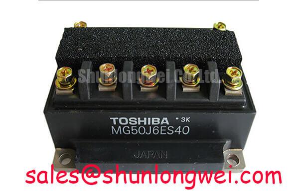
With the equipment isolated and its DC bus discharged, compare the installed module’s terminal labels with the original equipment schematic before taking a cold resistance reading. MG50J6ES40 is identified here as a Toshiba IGBT module with a 600 V voltage rating and a 50 A current rating (Official Specification). Its case designation is Toshiba Module; the available product information does not establish its terminal map, internal circuit, mounting dimensions, or gate drive limits. Those details need confirmation against the exact Toshiba documentation and the equipment assembly drawing before installation.
On the bench, begin with the driver disconnected. Record the resistance between accessible power terminals and between each identified gate and its corresponding emitter, following the verified terminal map. A reading that differs from a documented, known-good assembly warrants investigation, but a handheld meter alone cannot establish switching performance. For a diode-mode check, confirm the diode’s position and polarity from the circuit documentation first; do not interpret a forward-voltage reading as a pass or fail result without a specified test condition or a sound comparison unit.
💡 Bench Tip: Keep the gate terminals protected from static discharge and record the meter model and probe polarity so a cold-state comparison can be repeated consistently.
Desaturation detection belongs to the surrounding gate-driver protection circuit. As a Design Consideration, distinguish a fault detected during an established on-state from one occurring while the device is first commanded on: blanking, current rise, and the measured collector-emitter voltage can affect how the driver interprets each event. The available product information does not specify a short-circuit withstand time or a required fault-clearing interval for MG50J6ES40, so neither should be inferred from another module’s data. The equipment designer should establish protection timing using the applicable device documentation and measured waveforms.
A controlled or staged turn-off can be evaluated as a Design Consideration where rapid interruption produces excessive inductive voltage overshoot. Capture the fault signal, gate-to-emitter voltage, collector-to-emitter voltage, and DC-bus voltage with appropriately rated instrumentation. Compare peak device voltage with the 600 V rated boundary (Official Specification), while allowing for measurement uncertainty and operating variation. Keep high-current paths compact and maintain creepage and clearance appropriate to the complete assembly; this product information does not establish board-layout distances. For background on the switching behavior relevant to that assessment, see The Ultimate IGBT Knowledge Base.
Benchtop Waveform Tuning: Checking Drive Returns and Commutation Paths
Trace the actual terminals before treating MG50J6ES40 as a dual-IGBT circuit or assuming it provides an auxiliary Kelvin emitter connection. Neither arrangement is established by the available product information. If the verified terminal drawing shows a separate emitter-sense terminal, route its driver return independently of the main load-current path as a Design Consideration. This limits the extent to which voltage developed in the power path is added to the gate-driver reference. If no such terminal exists, do not create a substitute connection based on a visually similar module.
For a powered waveform check, use the equipment’s specified operating sequence and measure at the device terminals rather than relying only on a waveform at the driver board. Compare gate voltage, collector voltage, and current at the same operating point. Ringing can involve several interacting contributors, including commutation-loop inductance, gate-drive behavior, probing technique, and the surrounding circuit. A waveform that changes when the probe ground lead is moved should prompt a measurement-setup check before a hardware change.
Likewise, do not assume this module’s internal circuit contains a freewheel diode. If the verified drawing shows one, its reverse-recovery behavior should be assessed in the installed commutation path: an abrupt current transition can contribute to voltage ringing and radiated interference. A recovery softness factor or an EMC result cannot be assigned to MG50J6ES40 from the ratings provided here. An RC snubber may be evaluated as a Design Consideration if switching measurements show an unwanted transient, with its component values determined and checked in the complete system.
Phase-angle conduction control, line-frequency ripple smoothing, and thyristor gate-trigger measurements apply only where the surrounding equipment actually uses those functions. They are not properties established for this IGBT module. When reviewing a light-industrial automation drive or multi-joint robotic articulator, first identify the equipment topology and its control schematic; then compare observed waveforms with that topology rather than imposing tests intended for a different power stage.
Preventing Spurious Faults: Thermal Interface and Mounting Checks for MG50J6ES40
Before removing an installed unit, record its orientation, terminal connections, fastener positions, and the condition of the mating heat-sink surface. The designation Toshiba Module does not, by itself, confirm a particular baseplate shape or mounting-hole pattern. Check the mechanical drawing for the exact MG50J6ES40 assembly before selecting hardware or preparing a thermal interface.
If that drawing specifies a grease-mounted baseplate, clean the mating surfaces and apply the approved interface material evenly as a Design Consideration. The aim is to avoid trapped air and an excessively thick bond line while accommodating the documented surface geometry. A grease thickness of 50–100 µm must not be treated as a Toshiba requirement for this model: no model-specific interface thickness is established in the information provided. Use the manufacturer’s mounting instructions for material, quantity, fastener sequence, and final torque.
⚠️ Field Alert: Do not tighten the module to an assumed torque value when the exact mounting instruction is unavailable.
If temperature-related trips appear after installation, inspect both the electrical measurements and the mechanical contact. Compare case or heat-sink temperature readings under repeatable load conditions, confirm that the cooling path is unobstructed, and check whether mounting pressure appears even. A fault indication that changes with load does not, on its own, identify grease coverage as the cause; gate-drive faults, sensing errors, and changes in the load can produce similar observations.
During a service-parts review, MG100Q1ZS40 can be documented as a separate Toshiba module for comparison, not as a confirmed substitute. Replacement eligibility depends on the verified internal circuit, terminal layout, mechanical fit, electrical limits, thermal characteristics, and the equipment maker’s approval. Matching a brand name or one rating is insufficient.
Preventing Spurious Faults: DC-Bus Voltage Headroom for MG50J6ES40
Measure the DC bus in the equipment state that produces the highest expected voltage, then capture switching peaks at the module terminals using probes rated for the task. The 600 V rating (Official Specification) is a device voltage boundary, not a recommended continuous DC-bus setting. As a Design Consideration, account for bus variation and turn-off overshoot together; the permissible operating point must be set from the complete Toshiba data and verified by the system engineer under relevant operating conditions.
For an unexplained overvoltage trip, correlate the bus trace with gate commands, load current, and the fault timestamp. An elevated bus before switching calls for a different investigation from a brief peak coincident with turn-off. Check the measurement reference and probe bandwidth before interpreting a narrow spike. Review commutation-path layout and any installed snubber only after the waveform has been reproduced reliably.
Altitude and radiation effects should not be converted into a MG50J6ES40 derating percentage or a single-event-burnout failure rate without applicable manufacturer or qualified reliability data. No such figures are established by the product information used here. If the equipment has an altitude requirement, the system designer should obtain the relevant device and insulation documentation, assess cooling and electrical clearances at the installation site, and validate the resulting DC-bus operating limit in the assembled drive.