Content last revised on February 10, 2026
MG50J2YS9: A Technical Review of the 600V/50A Dual IGBT Module for Industrial Applications
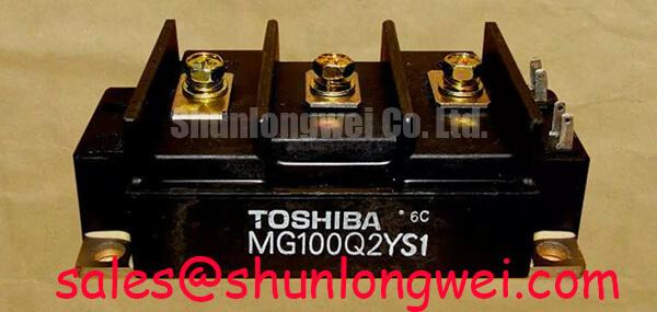
The Toshiba MG50J2YS9 is a robust dual IGBT module designed to deliver reliable performance in medium-power conversion systems. With core specifications of 600V | 50A | VCE(sat) of 2.7V, this component is engineered for longevity and thermal stability. Its key benefits include a high-reliability package and effective thermal dissipation characteristics, directly addressing the need for durable power stages in demanding industrial environments. What is the primary benefit of its integrated design? It simplifies circuit layout and enhances thermal management in a compact footprint. For cost-sensitive industrial motor drives up to 15 kW requiring proven reliability, the MG50J2YS9 offers a robust and thermally stable power stage.
Key Parameter Overview
Decoding the Specs for Thermal and Electrical Stability
The technical specifications of the MG50J2YS9 highlight its suitability for high-stress industrial applications. The module's ratings are carefully balanced to provide a dependable foundation for power circuit design, with an emphasis on thermal performance and safe operating limits.
| Parameter | Value | Engineering Implication |
|---|---|---|
| Collector-Emitter Voltage (Vces) | 600V | Provides sufficient voltage margin for applications running on 200/230V AC lines. |
| Collector Current (Ic) | 50A | Supports medium-power motor drives and power supplies. |
| Collector-Emitter Saturation Voltage (VCE(sat)) | 2.7V (Max) | Defines the primary conduction loss, a critical factor for thermal design and overall system efficiency. |
| Thermal Resistance (Rth(j-c)) | 0.625 °C/W per IGBT | Indicates efficient heat transfer from the semiconductor junction to the case, simplifying heatsink selection. |
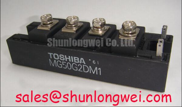
| Package Type | Dual IGBT Module | Integrates two IGBTs in a half-bridge configuration, ideal for inverter leg designs. |
Application Scenarios & Value
Achieving System-Level Reliability in Motor Control
The MG50J2YS9 is best suited for applications where long-term reliability and robustness are prioritized over cutting-edge switching efficiency. Its design provides a stable and predictable power stage for a variety of industrial systems. For systems that demand higher power output and voltage, the related MG150Q2YS50 offers a higher current and voltage rating.
A primary application for this module is in Variable Frequency Drives (VFDs) for AC induction motors used in conveyor systems, pumps, and fans. In a VFD, the inverter stage is subjected to continuous high-current Pulse Width Modulation (PWM) signals. The engineering challenge is managing the heat generated from both switching and conduction losses to prevent component degradation. The MG50J2YS9's thermal resistance of 0.625 °C/W is crucial here. It ensures that the heat generated at the IGBT junction can be efficiently conducted away to the heatsink, maintaining a junction temperature within the Safe Operating Area (SOA) and ensuring operational longevity.
Frequently Asked Questions (FAQ)
Engineering-Focused Inquiries for the MG50J2YS9
What is the direct impact of the 2.7V VCE(sat) on thermal design?
The VCE(sat) value is a primary determinant of conduction losses (P_cond = VCE(sat) * Ic). A VCE(sat) of 2.7V at 50A means that under full load, each IGBT will dissipate a significant amount of power as heat. Engineers must use this value to calculate the required performance of the heatsink to keep the junction temperature below its maximum rating, ensuring the module does not overheat and fail prematurely.
How does the "dual module" or half-bridge configuration simplify inverter design?
A dual IGBT module contains two IGBTs and two freewheeling diodes, typically arranged as a half-bridge. This configuration is the fundamental building block for one phase of a three-phase inverter. Using a single module instead of four discrete components (two IGBTs, two diodes) reduces assembly complexity, minimizes stray inductance by shortening connections, and simplifies thermal management as both devices are mounted on a single, shared baseplate.
What are the typical gate drive requirements for the MG50J2YS9?
While the datasheet provides specific values, IGBTs of this class typically require a gate voltage of +15V for full turn-on and either 0V or a negative voltage (e.g., -5V to -15V) for a secure turn-off. A negative gate voltage is often recommended in noisy environments to prevent unintended turn-on caused by Miller capacitance. The gate driver circuit must be capable of supplying sufficient peak current to charge and discharge the IGBT's input capacitance quickly to minimize switching losses.
For which applications is the 600V Vces rating most appropriate?
A 600V rating is primarily intended for power conversion systems connected to 200V-class AC lines (e.g., 208V, 230V, or 240V). After rectification, these line voltages result in a DC bus voltage of approximately 300-340V. The 600V Vces provides a substantial safety margin to withstand voltage spikes caused by stray inductance during high-speed switching events, making it a reliable choice for industrial inverters and servo drives operating on these common voltages.
Technical Deep Dive
A Closer Look at Thermal Design and Package Reliability
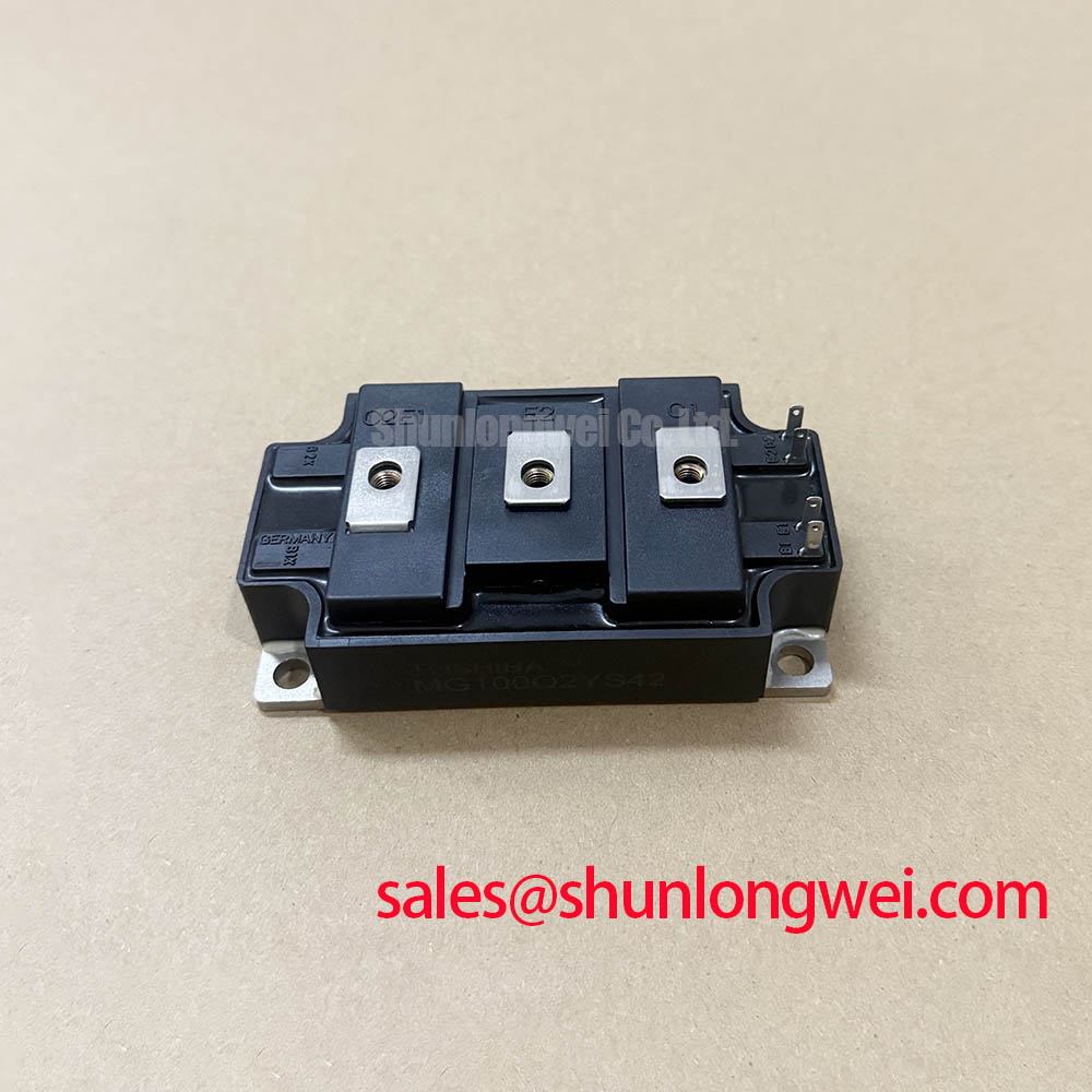
The long-term reliability of a power module like the MG50J2YS9 is fundamentally tied to its thermal management capabilities. The module's construction is optimized for efficient heat extraction. The core of this is the low Thermal Resistance from junction to case (Rth(j-c)). One can think of Rth(j-c) as the width of a pipe for heat flow; a lower value represents a wider pipe, allowing more heat to escape from the silicon chip to the module's baseplate with less temperature rise.
This efficient heat transfer is enabled by the module's architecture, which typically features a ceramic isolation layer (like Aluminum Nitride or Alumina) bonded to a copper baseplate. This structure not only provides excellent electrical isolation between the live terminals and the heatsink but also serves as an effective thermal conductor. The large, flat copper baseplate then ensures a solid, low-resistance thermal connection to the system's heatsink. What is the system-level advantage? This robust thermal path allows the module to handle transient power overloads and sustain continuous operation at high currents without exceeding its maximum junction temperature, a cornerstone of reliable design in applications like welding power supplies and uninterruptible power supplies (UPS).
While newer technologies offer lower switching and conduction losses, modules like the MG50J2YS9 retain their strategic importance. They provide a cost-effective, proven, and highly reliable solution for a vast range of industrial applications where system longevity and robustness are the primary design drivers. For engineering teams maintaining or developing systems in the medium-power range, this module represents a known quantity with predictable performance and a durable physical design, minimizing project risk and ensuring stable field operation.