


Content last revised on February 2, 2026
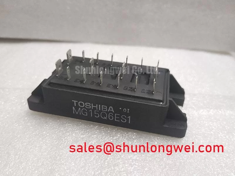
MG15Q6ES1 IGBT Module: Technical Data for 1200V/15A Power Systems
Product Overview: Key Specifications and Engineering Value
Delivering Robust Performance for General-Purpose Power Conversion
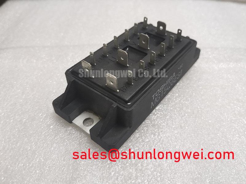
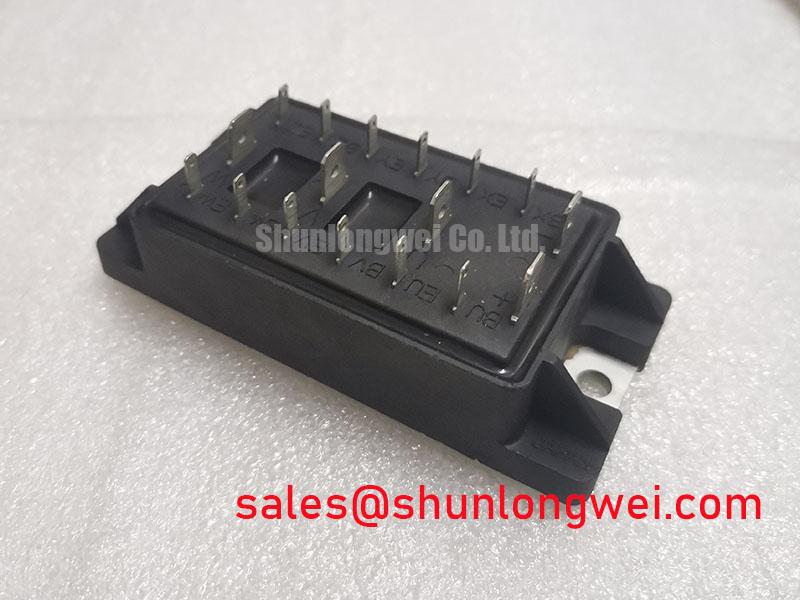
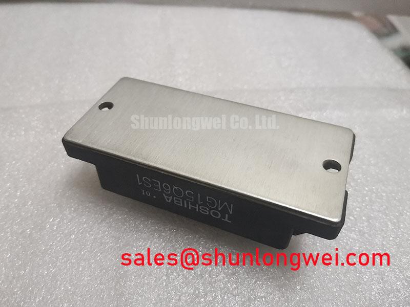
The MG15Q6ES1 is a high-voltage N-channel IGBT module engineered for reliability in demanding power switching circuits. It provides a robust solution for designers working on motor controls, inverters, and general-purpose switching applications where high voltage blocking capability is a primary requirement. Its key specifications include a 1200V collector-emitter voltage, a 15A continuous collector current, and a VCE(sat) of 4.0V (max). This translates into two core engineering benefits: exceptional voltage overhead for system safety and a proven, straightforward design for power stage implementation. For systems requiring robust performance in low-to-mid frequency switching applications, the MG15Q6ES1 offers a well-defined and reliable core component. This module is an optimal choice for cost-sensitive 1-3 kW motor drives operating on 400V or 480V industrial lines.
Key Parameter Overview
Decoding the Specs for System Design and Reliability
The technical specifications of the MG15Q6ES1 define its performance envelope. The table below highlights the critical parameters that directly influence system efficiency, thermal management, and switching behavior. Particular attention should be given to the thermal resistance and saturation voltage, as these figures are crucial for effective heatsink design and calculating conduction losses.
| Parameter | Symbol | Value | Unit | Conditions |
| Collector-Emitter Voltage | VCES | 1200 | V | VGE = 0V |
| Gate-Emitter Voltage | VGES | ±20 | V | VCE = 0V |
| Collector Current (DC) | IC | 15 | A | Tc = 25°C |
| Collector Power Dissipation | PC | 125 | W | Tc = 25°C |
| Collector-Emitter Saturation Voltage | VCE(sat) | 4.0 | V | IC = 15A, VGE = 15V |
| Input Capacitance | Cies | 1400 | pF | VCE = 10V, VGE = 0V, f = 1MHz |
| Turn-On Time | ton | 0.4 | µs | Inductive Load |
| Turn-Off Time | toff | 1.0 | µs | Inductive Load |
| Thermal Resistance (Junction-Case) | Rth(j-c) | 1.0 | °C/W | IGBT |
Download the MG15Q6ES1 datasheet for detailed specifications and performance curves.
Application Scenarios & Value
Achieving System-Level Benefits in Industrial Motor Drives
The MG15Q6ES1 is well-suited for legacy and new designs in the low-to-mid power range, particularly where simplicity and voltage robustness are prioritized over cutting-edge efficiency. What is the MG15Q6ES1's primary voltage rating? It is a 1200V device, making it ideal for systems operating on 400V and 480V industrial mains.
A primary application is in small Variable Frequency Drives (VFDs) for AC induction motors. In this context, an engineer's challenge is managing the voltage spikes caused by the motor's inductance during switching. The 1200V VCES rating of the MG15Q6ES1 provides a substantial safety margin, mitigating the risk of avalanche breakdown and enhancing the drive's long-term reliability. Its moderate switching speed is fully compatible with the typical Pulse Width Modulation (PWM) frequencies used in these drives (2-8 kHz), ensuring effective motor control without generating excessive switching losses. Other key applications include:
- Uninterruptible Power Supplies (UPS)
- Switching Mode Power Supplies (SMPS)
- General-purpose inverters
While the MG15Q6ES1 provides a solid foundation for these applications, for systems demanding higher current capacity or enhanced thermal performance, the QM50DY-H offers a higher current rating within a similar voltage class.
Technical Deep Dive
Balancing Conduction Losses and Switching Performance
A critical aspect of designing with the MG15Q6ES1 is understanding the trade-off dictated by its VCE(sat) value. The maximum saturation voltage of 4.0V at 15A is a key determinant of conduction losses. Think of VCE(sat) as the "toll" the current pays to pass through the device when it's fully on. A higher toll means more energy is converted to heat. For an application with a high duty cycle where the IGBT is "on" for long periods, this heat must be managed effectively through the heatsink, guided by the Rth(j-c) value. While a lower VCE(sat) is generally desirable for efficiency, the technology used in the MG15Q6ES1 prioritizes a high breakdown voltage and robust performance, making it a dependable choice for applications where this balance is acceptable. This characteristic makes it essential to perform careful thermal calculations to ensure the junction temperature remains within its safe operating area under all load conditions.
Frequently Asked Questions (FAQ)
What are the implications of the 4.0V maximum VCE(sat) on thermal design?
A VCE(sat) of 4.0V at 15A results in 60 watts of conduction loss (P = V * I) at full load. This requires a robust thermal management solution. Engineers must select a heatsink with a low thermal resistance to ensure the device's junction temperature stays well below the 150°C maximum, ensuring system reliability and longevity.
Why is the collector-emitter leakage current (ICES) specified at a VCE of 1200V?
The ICES specification (1mA max at Tj=125°C) demonstrates the device's ability to effectively block the high voltage in its "off" state. This is a critical parameter for ensuring minimal power leakage and preventing thermal runaway in high-voltage applications, confirming the quality of the silicon and its suitability for 1200V operation.
What are the key considerations for the gate drive circuit for the MG15Q6ES1?
The recommended gate-emitter voltage (VGE) is +15V for turn-on. A proper gate drive design should provide this voltage with sufficient peak current to charge the input capacitance (Cies = 1400 pF) quickly for efficient switching. It is also critical to ensure a solid "off" state, typically using 0V or a small negative voltage, to prevent unintended turn-on due to noise or Miller effect.
Strategic Fit and Application Focus
The MG15Q6ES1 holds a strategic position for designers and maintenance engineers who need a reliable, high-voltage switching component without the complexities of the latest generation technologies. Its value lies in its proven performance in foundational power applications like industrial motor control and power supplies. For new designs focused on cost-effectiveness and robustness, or for maintaining the operational life of existing equipment, the MG15Q6ES1 offers a well-documented and dependable solution, simplifying the design and procurement cycle.