

Content last revised on October 1, 2026
Preventing Spurious Faults: Voltage Headroom and Site Conditions for MIG30J103HA
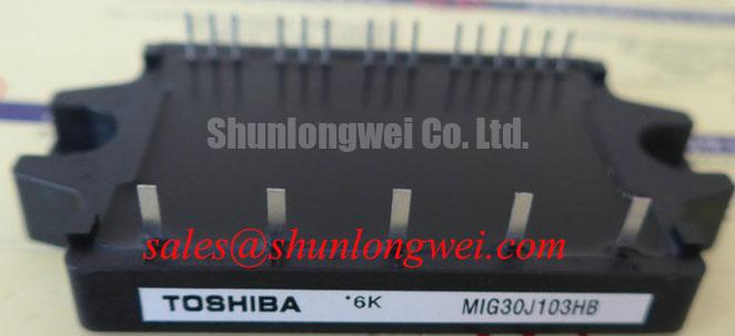
| Model | MIG30J103HA |
|---|---|
| Manufacturer | Toshiba |
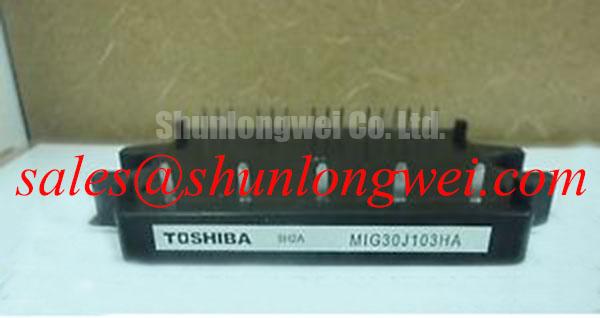
| Product category and package | Intelligent Power Module in a Toshiba Intelligent Power Module package |
| Rated voltage | 600 V (Official Specification) |
| Rated current | 30 A (Official Specification) |
Measure the DC link at the module terminals while reproducing the reported fault, then capture its highest switching transient rather than relying on the drive’s bus-voltage display. For MIG30J103HA, 600 V is the rated-voltage boundary (Official Specification); it is not a target operating bus voltage or permission to ignore turn-off overshoot. Record the probe connection and operating condition with each capture so a later comparison distinguishes a changing drive waveform from a changed measurement setup.
At the incoming bench, keep the module disconnected from the drive and identify its terminals against the equipment wiring diagram and the applicable Toshiba terminal drawing. Use a meter’s diode function to record cold-state conduction direction across each accessible power path, comparing equivalent paths only after their terminal functions have been established. A forward reading is useful as a baseline, not as proof that the module will switch correctly under load. Unexpected conduction in both directions calls for a second measurement with the meter leads reversed and the external wiring removed; connected snubbers, capacitors or motor circuits can otherwise confuse the result.
For equipment operating at altitude, treat cosmic-ray-related failure mechanisms and insulation spacing as separate design questions. A 600 V rating and a site elevation alone do not establish a single-event-burnout rate, an FIT figure or an altitude derating for this model. As a Design Consideration, the equipment engineer should review the actual DC-link waveform, site conditions and the applicable manufacturer reliability information before setting operating headroom. The safe operating area concept helps frame why voltage and current must be considered together during transients, but a general explanation cannot replace this module’s device-specific limits.
Inspect the board beneath the module for tracking, residue and damaged insulation before reconnecting high-voltage terminals. Creepage follows a surface; clearance is the shortest path through air. Both depend on the assembled drive, including contamination control, neighboring copper and barriers, rather than on the module’s voltage label alone. Where a fault appears only with a long motor cable, capture the waveform at the motor end as well as at the drive output. Reflections can produce a motor-terminal peak different from the module-terminal waveform; cable layout or an output filter should be evaluated against measured conditions, not chosen from the module rating in isolation.
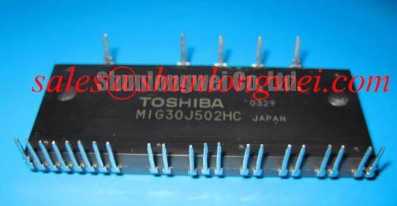
A replacement comparison needs the same discipline. The MIG150J6CSB1W can be examined as another Toshiba module during cross-model evaluation, but a different model number is not evidence of terminal, control, protection or mechanical interchangeability. Compare the original drive drawing, mounting interface and the complete electrical ratings before considering any change.
Preventing Spurious Faults: Desaturation and Gate-Interlock Checks for MIG30J103HA
Probe the drive’s fault output and gate-control signals together when a trip occurs during acceleration. Their order matters: a control-board shutdown followed by a falling output current suggests a different investigation from rising current followed by a fault indication. Check the signal against a known-good axis under the same operating condition, using an appropriately isolated measurement setup. Do not infer an internal desaturation threshold, short-circuit withstand time or shutdown sequence for MIG30J103HA from its 30 A rated current (Official Specification).
Trace the actual protection path on the drive schematic. Determine which circuit senses an overcurrent condition, which circuit inhibits the gate command and whether the control supply remains stable through the event. An optocoupler or digital isolator on the drive board is part of that system-level path; its common-mode transient immunity cannot be assigned to the module by association. When fault edges coincide with power-stage switching, inspect the isolator supply and reference waveform for disturbance before attributing the trip to a failed power device.
As a Design Consideration, turn-off must limit the voltage produced by current changing through the power-loop inductance. A drive may use staged fault turn-off, but its timing and gate behavior are determined by the installed driver and verified waveforms, not by a generic prescription for this model. Capture collector-to-emitter voltage and current during controlled testing, then compare the peaks with the relevant device limits and the drive’s protection response. If the original documentation does not establish a short-circuit operating boundary, do not assume a commonly quoted timing limit applies.
For complementary switches, check that the command logic and measured gate waveforms prevent overlap through switching transitions. Dead time that looks adequate at a controller pin may differ at the device after propagation delays and switching effects. Review gate-return routing and the separation of sensing from noisy power-current paths when investigating intermittent trips. These are Design Considerations for the assembled drive; the final timing belongs to its validated control and protection design.
💡 Bench Tip: Discharge the DC link and verify it with a meter before moving probes or disconnecting a module terminal.
Preventing Spurious Faults: Regenerative Braking and Thermal Cycling Checks for MIG30J103HA
Trend the DC-link voltage through a repeatable deceleration and note whether the fault occurs as the motor returns energy to the drive. In a high-dynamics multi-axis CNC or robotics servo, that observation can distinguish a regeneration-related event from a trip that first appears under motoring load. It does not establish that MIG30J103HA contains a braking switch. Locate the braking device and resistor on the actual power schematic before assigning either function to the module.
If the drive uses a braking chopper, inspect its command, the resistor connection and the bus waveform during deceleration. The resistor must be evaluated for the energy and repetition of the equipment’s duty cycle, while the switching device must be assessed against its documented electrical and thermal limits. Those are system-determined quantities. Avoid sizing a replacement resistor solely from the module’s 600 V and 30 A ratings (Official Specifications): neither states the motor’s returned energy nor confirms the braking circuit topology.
At the bench, compare cold diode-function readings across identified power paths, then inspect the terminal screws, bus connections and surrounding board for heat discoloration or looseness. A changed reading merits investigation, but one reading cannot identify the root cause of a braking fault. Likewise, an intermittent trip after repeated decelerations may involve resistor heating, a control signal, a connection or the main power stage. Log the bus waveform and the fault sequence before replacing parts.
Thermal cycling also acts on the assembled heat path and electrical connections. Check for uneven contact marks at the module-to-heatsink interface and for evidence of movement at external terminals. An appropriate insulation or surge-current assessment requires the relevant device ratings and test conditions; a cold meter check cannot establish insulation withstand, and the 30 A rating does not state a surge-current limit. For broader context on coordinating switching, protection and heat removal, the Power Electronics Masterclass provides a system-level engineering discussion rather than model-specific limits.
MIG30J103HA Thermal-Electrical Optimization: Interface Contact and Mounting Checks
Inspect the heatsink contact pattern when removing a module associated with a load-dependent temperature fault. Note dry areas, heavy deposits and debris before cleaning the mating surfaces; once the interface is disturbed, that evidence is difficult to recover. Check the replacement module’s mounting footprint and terminal alignment against the original assembly without forcing the case into position. A package description alone does not establish hole locations, screw size or allowable mounting torque.
As a Design Consideration, apply thermal interface material as a controlled, even layer intended to fill surface imperfections rather than a thick cushion between the mating faces. Inspect the heatsink for burrs and flatness issues that could prevent uniform contact. Follow the applicable module and equipment mounting instructions for screw sequence and torque, then check that tightening has not shifted the terminals or strained the board. The thermal interface material overview explains why material choice and contact quality affect heat transfer; it does not specify a required thickness for MIG30J103HA.
Recheck temperature behavior at comparable load, switching and cooling conditions after installation. A lower measured heatsink temperature at one point does not by itself establish a lower junction temperature: sensor location, airflow and interface contact affect the observation. If the drive trips as it warms, compare its temperature indication, output current and fault timing with a known-good operating record. Record the mounting materials and procedure alongside those measurements so the next technician can reproduce the assessment.
Complete the electrical check at the assembled terminals. Confirm that power connections match the original wiring drawing, that control connections have not been displaced during mounting and that required spacing remains clear of hardware and excess interface material. For drives with long motor cables or frequent regenerative cycles, repeat the waveform checks under those conditions; thermal repair does not remove a switching transient or braking-system fault elsewhere in the equipment.