Content last revised on September 10, 2026
Transient Thermal Impedance (Z_th(j-c)) & Multi-Layer Foster/Cauer Modeling
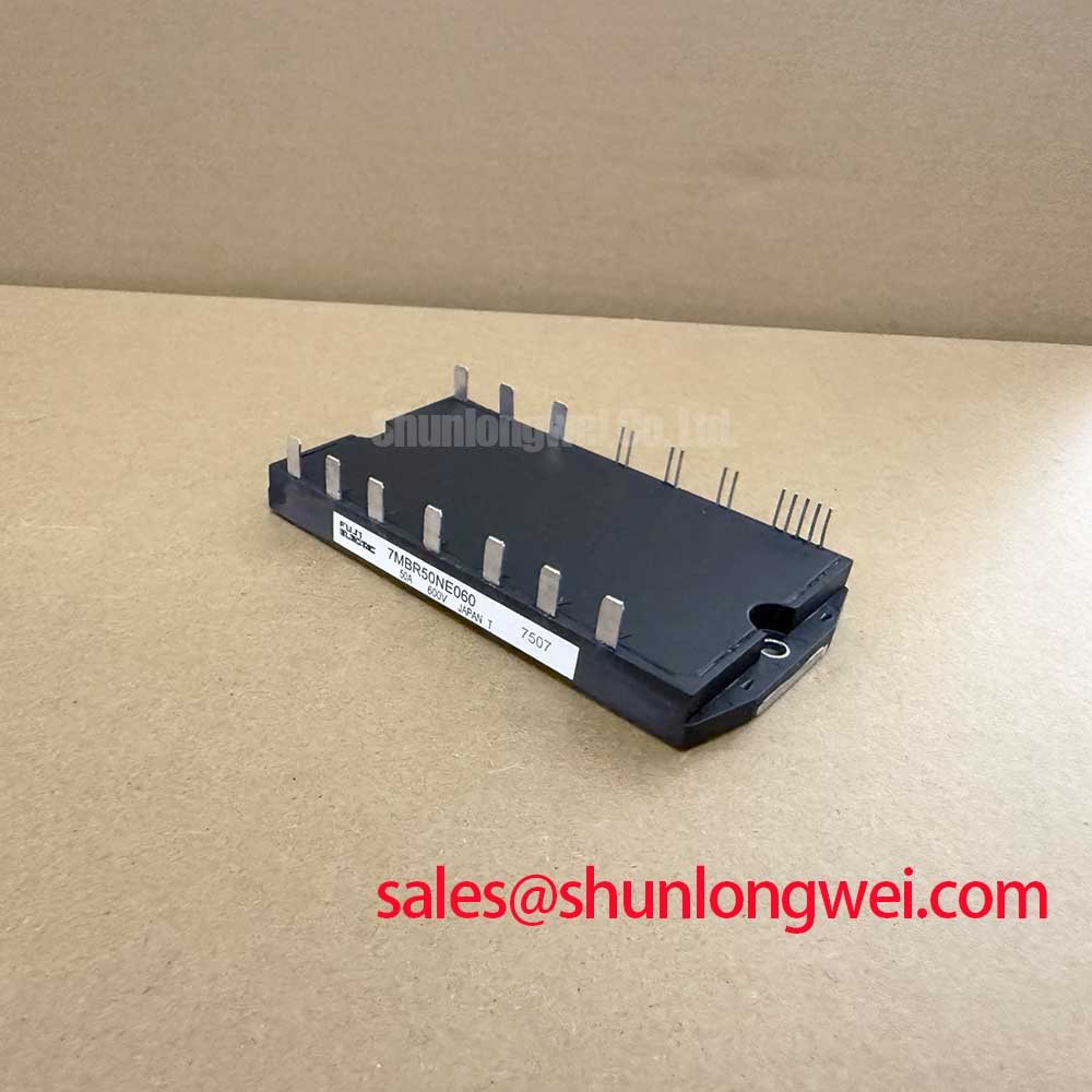
When emergency maintenance calls take you to a remote nacelle sitting 3,200 meters above sea level, unexpected pitch and yaw converter lockouts often point directly to thermal stress on compact power integration modules. The 7MBR20UF060 by Fuji Electric packs an entire three-phase input bridge, brake chopper, and three-phase inverter stage into a single Power Integrated Module (PIM) package. Rated at a maximum collector-emitter voltage of VCES = 600V (Official Datasheet Specification) and a continuous collector current of IC = 20A at Tc = 80°C (Official Datasheet Specification) with a maximum junction temperature rating of Tj = +150°C (Official Datasheet Specification), managing dynamic heat flow under gust-induced pitch braking cycles determines converter survival.
Field data reveals that pitch drive motors demand high-amplitude current pulses during emergency aerodynamic feathering. Under these surge events, the pulsed collector current reaches up to ICP = 40A (Official Datasheet Specification), causing rapid temperature spikes inside the silicon die. Because steady-state thermal resistance Rth(j-c) only reflects continuous conduction equilibrium, bench engineers and field technicians must evaluate the transient thermal impedance Zth(j-c). Under short-duration braking bursts lasting under 100 milliseconds, thermal energy concentrates within the silicon chip and the direct copper bonded (DCB) ceramic substrate before diffusing toward the copper baseplate.
To accurately capture this behavior during system diagnostics, multi-layer Foster and Cauer RC networks represent the thermal diffusion path through the silicon, solder interface, ceramic isolator, and baseplate. Foster models allow swift calculation of transient thermal impedance curves using partial thermal resistances and time constants extracted from factory test data, while Cauer models represent actual physical material layers. When running high-duty pitch maneuvers, individual element power dissipation must remain strictly within the collector power dissipation ceiling of Pc = 85W per element (Official Datasheet Specification).
During active troubleshooting, technicians should measure the temperature difference between the module casing (using an embedded NTC thermistor or an external thermal probe) and the heatsink base. If transient thermal impedance spikes unexpectedly during short duty cycles, solder layer fatigue or voiding beneath the IGBT die should be suspected. For detailed cross-sectional diagnostics and destructive physical analysis protocols, refer to the Field Engineer’s Handbook for established test criteria.
| Parameter | Datasheet Rating / Status | Engineering Identity |
|---|---|---|
| Collector-Emitter Voltage (VCES) | 600V | Official Datasheet Specification |
| Continuous Collector Current (IC @ Tc=80°C) | 20A | Official Datasheet Specification |
| Repetitive Pulsed Current (ICP) | 40A | Official Datasheet Specification |
| Collector Power Dissipation (Pc per element) | 85W | Official Datasheet Specification |
| Isolation Voltage (Viso, AC 1 min) | AC 2500V | Official Datasheet Specification |
| Maximum Junction Temperature (Tj(max)) | +150°C | Official Datasheet Specification |
Baseplate Convexity Compensation and Screw Tightening Sequence Guidelines
Mechanical installation in nacelle pitch cabinets is a major source of early-life module failure. The 7MBR20UF060 features an integrated copper baseplate designed with deliberate microscopic convexity. This manufacturing pre-bend ensures that as mounting screws are drawn down to specification, contact pressure pushes outward from the center, expelling air pockets and compressing the thermal interface material (TIM) into a uniform micro-layer.
⚠️ Field Alert: Applying uneven torque or overtightening a single mounting screw immediately cracks the internal ceramic DCB substrate or bows the baseplate edges upward, trapping a thick air cushion directly under the inverter IGBT dice. Never use power drill drivers without calibrated torque clutches when seating these modules onto the heatsink.
A controlled TIM application thickness between 50 μm and 100 μm is recommended (General Industry Design Consideration). Excessively thick thermal grease increases conductive thermal resistance, while insufficient grease leaves microscopic voids across surface machining ridges. To verify mounting flatness, technicians should perform a visual contact check using a backlit precision straightedge on the heatsink surface, verifying that heatsink planarity stays within 50 μm per 100 mm span prior to grease application.
The tightening process must follow a strict two-pass sequence. On the preliminary pass, all mounting screws should be hand-tightened to a pre-torque of approximately 1.0 N·m (Typical Starting Point for bench assembly). On the final pass, tighten diagonally opposite screws progressively to a final mounting torque of 2.5 to 3.5 N·m (General Industry Design Consideration for standard M4/M5 hardware). This allows the grease to squeeze out smoothly across the footprint without warping the module housing.
When selecting external gate drive damping resistors to manage switching transitions on the integrated brake chopper and inverter stages, an initial gate resistance RG around 10 Ω to 22 Ω serves as a stable starting baseline (Typical Starting Point for bench tuning). For higher power auxiliary subsystems or adjacent intermediate power stages requiring discrete building blocks, the 1MBI200NH-060 provides a representative reference for modular layout and thermal spreading behavior.
Optimizing Gate Drive Loop Geometry to Prevent Cross-Conduction Oscillation
In high-altitude wind turbine pitch mechanisms, electromagnetic interference generated by fast switching transients can compromise gate drive integrity. The 7MBR20UF060 integrates the entire inverter bridge into a dense pinout configuration. Parasitic inductance present in the gate-emitter loop interacts with the device's internal input capacitance and reverse transfer capacitance Cres (Miller capacitance), creating conditions favorable for spurious gate oscillation and catastrophic shoot-through.
Cross-conduction occurs when high turn-on di/dt from an active switch induces a positive voltage spike on the gate of the complementary off-state switch across the same phase leg. The high dv/dt transient charges the reverse transfer capacitance, injecting current directly into the off-state gate node. If the impedance of the turn-off gate path is too high, the gate voltage exceeds the gate threshold level VGE(th), turning both switches on simultaneously across the 600V DC link.
To suppress this vulnerability, the gate drive PCB layout must separate the auxiliary Kelvin emitter return pin from the main high-current power emitter trace. Route the gate feed and auxiliary Kelvin return lines as tightly coupled differential pairs or stacked layers on adjacent PCB planes to minimize total enclosed loop area. Incorporating active Miller clamping—or providing an active negative turn-off bias voltage of -5V to -8V (Design Consideration)—prevents parasitic turn-on during severe collector voltage transitions.
Technicians assessing retrofits in compact control racks can evaluate alternative pin topologies. For systems requiring discrete six-pack arrangements or different voltage margins, the related 6MBI10S-120 offers an alternative topology with 1200V blocking capability for higher DC bus configurations. Gate wiring should always maintain physical separation from high-current AC output leads to avoid inductive coupling during heavy acceleration or dynamic motor braking.
High-Altitude Cosmic Ray Induced SEB Failure & FIT Rate Mitigation
Operating power converters at elevations exceeding 2,000 to 3,000 meters exposes semiconductor power stages to significantly increased fluxes of terrestrial atmospheric neutrons. Energetic neutrons colliding with silicon atoms within the reverse-biased depletion region generate localized electron-hole plasma filaments. Under the influence of the internal electric field, this localized avalanche can trigger destructive Single Event Burnout (SEB), causing catastrophic module failure without prior over-temperature or over-current indications.
Standard semiconductor failure rates (expressed in Failures In Time, FIT, where 1 FIT = 1 failure per 109 component operating hours) multiply substantially when moving from sea level to mountain ridges above 3,000 meters. Because cosmic ray SEB vulnerability increases exponentially with the applied DC-link electric field strength, the primary countermeasure in high-altitude wind converter design is DC bus voltage derating.
For a 600V rated module such as the 7MBR20UF060, continuous DC-bus operational voltage should be derated to approximately 350V to 400V under nominal conditions (General Industry Design Consideration for high-altitude derating). Running a continuous DC voltage above 480V at high elevations significantly elevates the risk of random cosmic ray breakdown over long operating lifespans.
Air density reduction at 3,000 meters also impacts clearance, creepage distances, and convective cooling efficiency. According to insulation coordination principles outlined in IEC 60664-1, dielectric clearance distances must be multiplied by altitude correction factors (such as 1.25 to 1.48 for 3,000m) to maintain the module's rated AC 2500V (1 min) (Official Datasheet Specification) isolation integrity. Air-cooled heatsinks must also be oversized to compensate for lower air mass flow.
During field service audits of wind converter enclosures, optical inspection tools and thermal diagnostic cameras are frequently used to evaluate baseplate hotspots and degradation. Calibrating these optical inspection monitors according to standard reference standards, such as Color Temperature and White Point Calibration in Displays, ensures field technicians accurately interpret true color variations in thermal images and component surface discoloration during preventative maintenance.
When swapping modules during field repairs, verify that the module terminal pins are free from mechanical strain, that heatsink surfaces are thoroughly degreased with isopropyl alcohol, and that dynamic DC overvoltage snubbers are fully functional before re-energizing the converter stage.