

Content last revised on September 22, 2026
7MBR50NE060 Module Identification and Initial Inspection
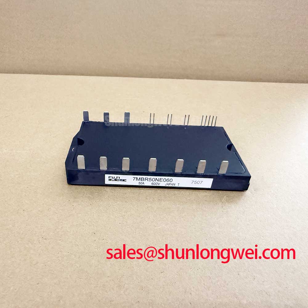
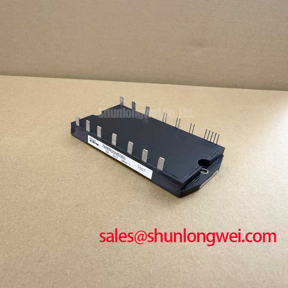
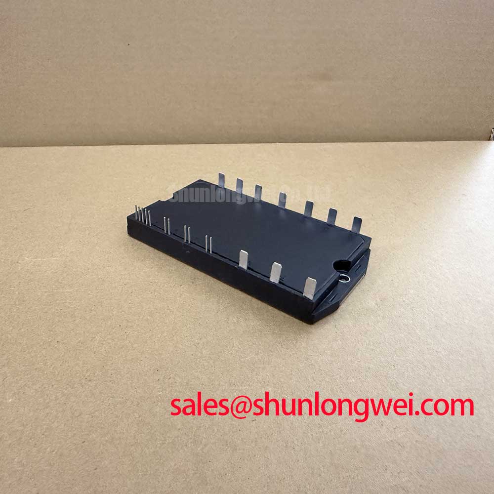
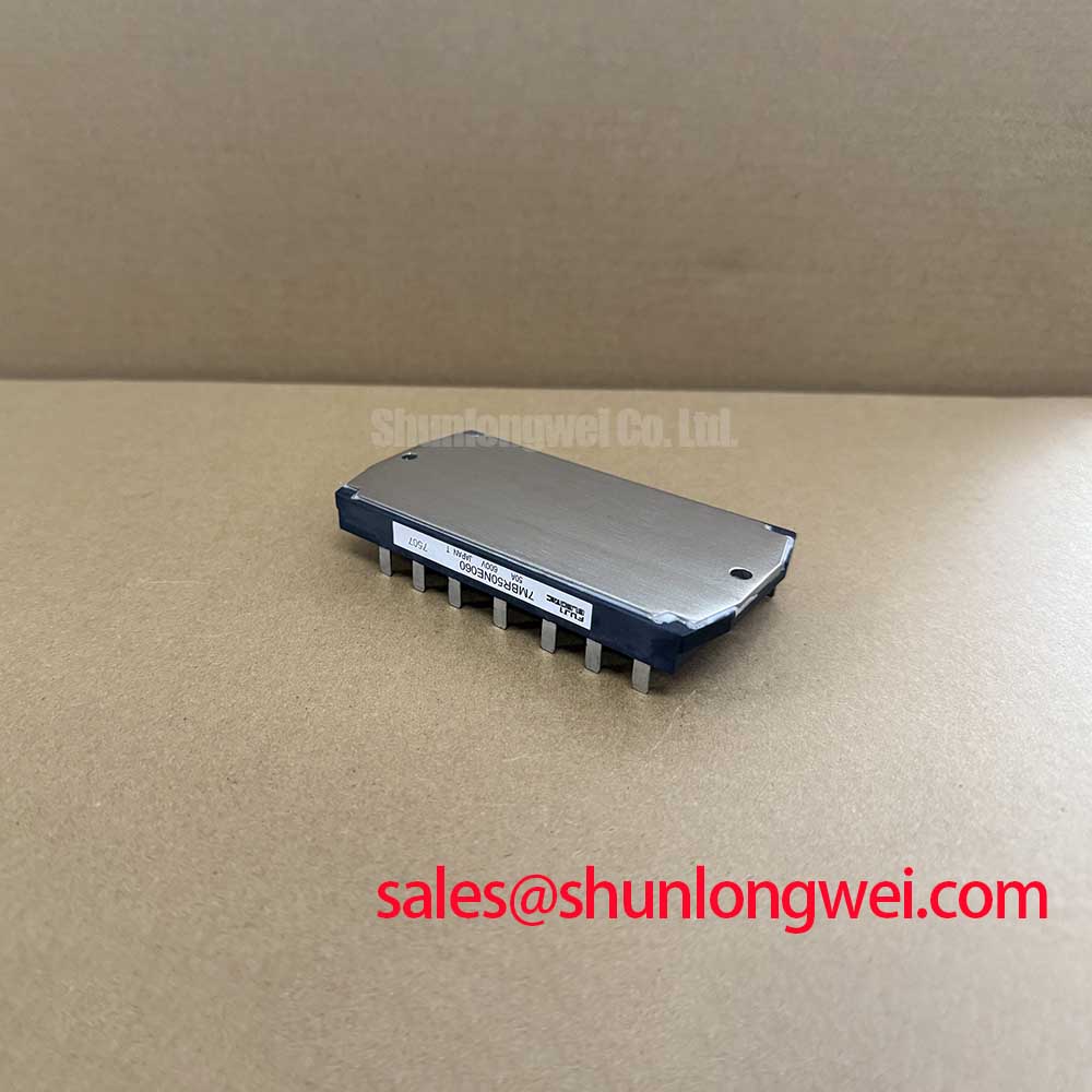
With the drive cabinet isolated and the DC link confirmed discharged, begin by checking the 7MBR50NE060 module for cracked housing surfaces, loose power terminals, heat sink witness marks, and abnormal cold-state resistance paths before reconnecting any gate-drive wiring. This Fuji Electric power module is officially rated at 600.0 V and 50.0 A; those ratings are the electrical identity to verify against the original inverter documentation before a repair decision is made.
| Manufacturer | Fuji Electric |
| Model | 7MBR50NE060 |
| Product Category | Power Module |
| Rated Voltage | 600.0 V Official Datasheet Specification |
| Rated Current | 50.0 A Official Datasheet Specification |
| Package | Module Official Datasheet Specification |
For a failed light-industrial automation drive or multi-joint robotic articulator controller, the module part number alone does not establish a safe replacement. The repair engineer should compare the original module outline, power-terminal arrangement, control-terminal assignment, driver interface, heat-sink contact area, and system bus conditions with the equipment documentation. Fuji Electric provides its relevant semiconductor product context through its Power Semiconductor and IPM Modules information resource.
Benchtop Waveform Tuning and High Altitude Stress Review for 7MBR50NE060
Before applying operating power, use a controlled cold inspection to separate obvious module faults from surrounding driver-board, cable, motor, or DC-link faults. With the module disconnected as required by the equipment service procedure, compare resistance readings between accessible power terminals against the corresponding positions of a known-good circuit or an equivalent unpowered phase leg. A low-resistance reading can indicate a damaged switching path, but it can also reflect parallel components on the controller board. Measurements should therefore be interpreted with the module’s installation context in mind rather than treated as a standalone pass or fail result.
The official 600.0 V rating establishes the module voltage class, not a complete DC-bus design allowance. Bus voltage, switching overshoot, regenerative events, wiring inductance, clamp behavior, and the selected driver protection response are determined by the assembled equipment. During a bench restart, engineers should measure the actual collector-emitter switching waveform with an appropriately rated differential probe and compare the observed peaks with the controller’s intended operating limits. Probe grounding and placement matter because a poorly arranged measurement loop can display ringing that is largely created by the test setup.
High-altitude operation requires particular caution because installation conditions may affect insulation coordination, enclosure clearance, cooling behavior, and system-level voltage margins. No altitude derating curve, terrestrial neutron response, single-event burnout limit, or failures-in-time value is included in the supplied product information for this model. It would therefore be inappropriate to assign a numeric FIT rate or a mandatory bus-voltage derating figure to the 7MBR50NE060. As a Design Consideration, equipment engineers should evaluate the complete converter against its own environmental requirements, insulation system, local installation rules, measured electrical stress, and applicable manufacturer documentation.
Gate-loop behavior should be examined on the hardware rather than assumed from another inverter platform. Gate resistance, driver output capability, gate return routing, and power-loop inductance collectively influence switching speed and ringing. If repeated gate waveform oscillation is seen, it may indicate an interaction among the driver, layout, power-stage condition, and measurement method. The practical response is to inspect the gate return path, confirm driver-board component condition, and validate the waveform against a known-good channel where possible. Any adjustment to gate damping or active clamping is an Engineering Recommendation subject to switching tests, not an official parameter of this module.
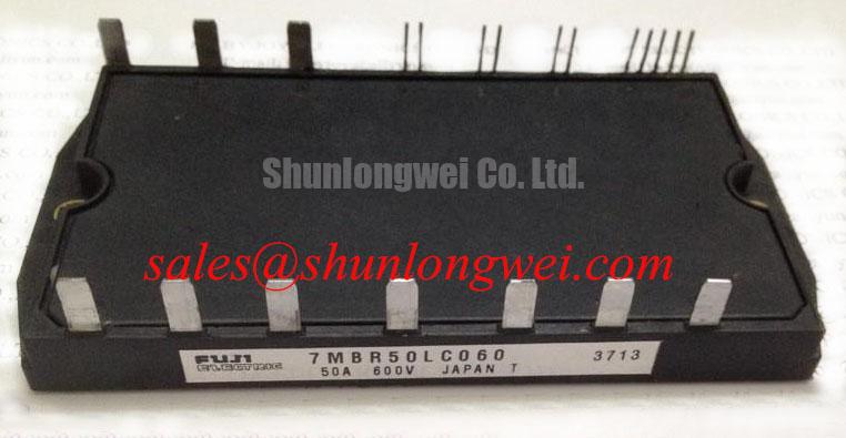
For engineers comparing existing service options, the 7MBR50LC060 is a related Fuji Electric module reference that requires independent confirmation of electrical ratings, terminal geometry, driver compatibility, and mechanical fit before it is considered in any repair evaluation. Similar part numbering does not establish direct interchangeability in a working drive.
Assembly Integrity and Layout Architecture for 7MBR50NE060
Mechanical assembly begins at the heat-sink interface. Remove old thermal compound without gouging the mounting surface, inspect the heat sink for flatness and contamination, then apply thermal interface material according to the equipment maker’s procedure. Uneven compound coverage, debris, or a distorted mounting surface can create localized thermal resistance that is not apparent during a short no-load start. The module housing should sit fully on the intended mounting plane before fasteners are tightened in a balanced sequence.
Field Alert: Tighten module hardware only to the torque specified for the actual fastener and assembly drawing, and keep the thermal compound layer uniform so that mechanical force is not concentrated at one area of the module base.
The supplied official information confirms a Module package but does not provide junction-to-case thermal impedance curves, transient thermal capacitance data, maximum junction temperature, mounting torque, or switching-loss values. These characteristics must be taken from the exact Fuji Electric documentation associated with the installed assembly. It is not technically sound to calculate a peak junction-temperature margin for this part from current rating alone. A valid thermal assessment needs the actual load profile, switching conditions, cooling path, heat-sink performance, ambient environment, and the relevant thermal curves.
In equipment that carries pulsed motion loads, a short operating test can conceal heat accumulation that emerges during repetitive acceleration, braking, or frequent axis reversals. As a Design Consideration, monitor the controller’s available temperature feedback, airflow condition, heat-sink cleanliness, and operating waveform while reproducing the real duty cycle. If an inverter trips only after a period of movement, examine both thermal transfer and control conditions. A clogged air path, a failing fan, a loose temperature-sensor connection, excessive switching loss, or a motor-side fault can produce overlapping symptoms.
Switching frequency should not be selected from a module current rating. Higher switching activity can alter loss distribution and cooling demand, while lower switching activity can change acoustic, current-ripple, and control behavior. The system engineer should verify switching-frequency suitability using the applicable module curves and the measured electrical conditions of the repaired equipment. The 50.0 A official current rating is valuable for part identification, yet it does not replace an application-specific thermal and switching-loss review.
Layout work should also protect serviceability. Keep driver connections routed as intended by the original equipment design, preserve isolation spacing, and avoid routing signal wiring beside high-current paths where maintenance changes could increase noise coupling. If the drive has suffered a power-stage failure, inspect the DC-link capacitors, busbar hardware, snubber components, gate-driver supply, motor cable, and load for collateral damage before placing a replacement module at risk.
Field Diagnostics and Commissioning for 7MBR50NE060 Topologies
A module replacement should not be the first powered diagnostic step after a drive fault. First establish whether the controller reports a gate-drive, overcurrent, DC-link, phase-loss, thermal, encoder, or motor-related alarm. Alarm labels vary by equipment maker, and one indication can originate from multiple fault paths. Review the event record if available, inspect burned or discolored driver-board components, and compare each phase circuit with a known-good section before applying full bus voltage.
Desaturation protection and short-circuit response belong to the gate-driver and converter architecture. The supplied specifications do not state the short-circuit safe operating area, desaturation threshold, protection delay, or soft-turn-off profile of the 7MBR50NE060. Claims about a fixed sub-microsecond or multi-microsecond clearing time would not be supported by the available official data. The appropriate Engineering Recommendation is to verify that the installed driver protection circuit, gate supply, fault latch, and controlled shutdown behavior match the equipment manufacturer’s design documentation.
During commissioning, begin with the least stressful test permitted by the system procedure. Confirm control power, driver supply integrity, interlock behavior, and command inhibition before energizing the main power stage. When waveforms are checked, compare phase-leg behavior under the same command condition. Unequal gate amplitude, a delayed switching edge, or unexpected collector-emitter behavior may indicate a driver-channel issue, a connector problem, a damaged gate path, or a difference in the power circuit. An oscilloscope comparison against a known-good signal path is more useful than relying on a single meter reading.
Soft turn-off is often used at the driver level to manage stored energy during an abnormal current event. Its implementation is not a universal module setting. Driver circuitry, bus voltage, stray inductance, clamp network, and system protection requirements must be assessed together. If a repaired drive has repeated driver faults after module replacement, stop repeated restart attempts and inspect the fault-clearing path. Repeated uncontrolled energization can damage a replacement module even when the original event began outside the module.
Where a converter contains an associated front-end or auxiliary power stage, the 6MBI100L-060 can be reviewed as a separate related power-module reference. Its presence in a different circuit does not establish identical function or replacement suitability. Verify each circuit’s topology, ratings, terminal mapping, and control method individually.
Preventing Spurious Faults Through Symmetrical Busbar Geometry for 7MBR50NE060
Unexpected overvoltage alarms, noisy current feedback, gate ringing, and irregular switching can arise from the interaction between busbar geometry, DC-link placement, driver routing, and measurement practice. At turn-off, the peak voltage is influenced by DC-bus voltage plus the inductive effect of the commutation loop and changing current. In practical terms, more loop inductance and a faster current transition can increase overshoot. This is an Engineering Calculation principle, but a numeric peak estimate requires measured or validated loop inductance and switching current behavior from the actual assembly.
For the 7MBR50NE060, preserve the original power-loop geometry whenever possible during service. A replacement busbar that is longer, offset, loosely clamped, or incorrectly stacked can alter parasitic inductance and current sharing. Keep outgoing and return current paths closely coupled according to the original layout, ensure busbar contact faces are clean, and confirm that all terminal hardware is correctly seated. These measures help suppress turn-off inductive overshoot, but final peak-margin verification must be performed by the system engineer during switching tests.
Snubber networks and DC-link capacitors are system components, not generic accessories selected from the module’s 600.0 V and 50.0 A ratings. Their required capacitance, ESR, voltage capability, location, and damping behavior depend on the converter topology and measured switching event. If an existing snubber is cracked, heat-discolored, open, or mechanically loose, replace it only with the value and construction specified by the original equipment documentation. Altering it without validation can shift stress to the module, capacitors, or driver.
Symmetry is especially important when several power paths share a DC link. Inspect phase-bus lengths, fastening pressure, copper orientation, and capacitor connection placement for unintended differences introduced during repair. A current imbalance or one phase that behaves differently from the others may indicate layout variation, a driver issue, a sensor path problem, or a load-side condition. Diagnose with comparative measurements rather than assigning one cause from one waveform.
For broader repair and measurement principles concerning IGBT switching behavior, power-loop effects, and safe evaluation boundaries, consult The Ultimate IGBT Knowledge Base. The final decision for this module should remain anchored to the official 600.0 V, 50.0 A, and Module package identity, together with the original machine’s electrical, mechanical, and protection requirements.