How Much Does Rth Really Matter? The Untold Impact of Thermal Resistance in High-Power IGBT Module Selection
When was the last time you checked the Rth(j-c) value before finalizing your IGBT module choice? In high-density, high-power inverter projects, junction-to-case thermal resistance (Rth) is often overlooked—yet its impact on reliability and system lifetime is far more profound than many engineers realize.
Understanding Rth(j-c): The Thermal Bottleneck You Can’t Afford to Ignore
In the world of IGBT modules, Rth(j-c)—the thermal resistance from the chip junction to the case—serves as the critical bridge for heat transfer from the silicon die to your heatsink. It is measured in Kelvin per Watt (K/W), representing how much the junction temperature rises for each watt of power dissipated. See thermal resistance for more details.
Why does this matter? Because as you push for higher power density and more compact designs, every degree counts. Excessive junction temperatures accelerate silicon aging, reduce switching speed, and can even cause catastrophic failure. The lower your Rth(j-c), the more efficiently heat escapes, and the more power your system can safely handle—especially in compact, forced-air or even liquid-cooled environments.

Case Study: FF400R07KE4 – Engineering for Low Thermal Resistance
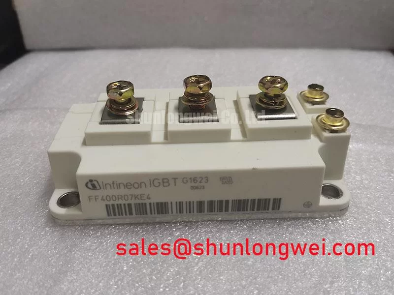
The FF400R07KE4 from Infineon is a textbook example of low-Rth engineering. Designed for demanding industrial drives and high-power inverters, it features:
- Rated voltage/current: 650V / 400A
- Rth(j-c): 0.035 K/W (per IGBT switch)
- Advanced packaging: EconoDUAL™3 optimized for minimal thermal resistance and stray inductance
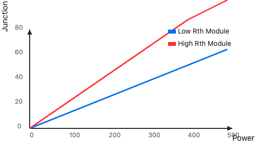
In practical terms, for every 100W of loss, the chip junction temperature rises only 3.5°C above the case. For a similar module with Rth=0.06 K/W, the rise would be 6°C. That seemingly small difference can define your entire thermal budget—especially as switching losses grow with frequency and current.
| Model | Rated Current | Rth(j-c) (K/W) | Heatsink Temp (°C) | Max Junction Temp (°C) | Thermal Margin |
|---|---|---|---|---|---|
| FF400R07KE4 | 400A | 0.035 | 75 | 110 | 35°C headroom at 100W loss |
| FF600R12IP4 | 600A | 0.045 | 75 | 119 | 44°C headroom at 100W loss |
| SKM600GB12M7 | 600A | 0.06 | 75 | 131 | 56°C headroom at 100W loss |
Note: Lower Rth means less junction overheating for the same power loss, which directly translates into longer silicon life and higher system safety.
Rth in High-Power Density Design: Not Just a Number, But a Design Enabler
So what? For hardware leaders aiming to shrink cabinet size or increase output per cubic centimeter, Rth is the margin that lets you push boundaries. Lower Rth allows:
- Smaller or less aggressive heatsinks (lower BOM cost, more compact enclosures)
- Higher allowable current peaks without risking junction overtemperature
- More reliable operation in harsh industrial environments (high ambient, poor airflow)
- Longer module lifespan due to reduced thermal cycling and lower peak temperatures
On the flip side, ignoring Rth can force you into overengineered cooling or premature module failure—either way, cost and performance suffer.
Thermal Design in Practice: How to Leverage Rth Effectively
Simply picking the lowest Rth module isn’t enough. Consider these steps:
- Calculate total power loss (conduction + switching) at your worst-case scenario.
- Sum up heatsink-to-ambient and module-to-case resistances for the total path.
- Model temperature rise at maximum load and ambient. Ensure Tj(max) never exceeds device ratings.
- Factor in real-world variables: aging, dust, fan failure, and mounting pressure.
In many cases, modules like FF400R07KE4 provide the best cost/performance balance for dense inverter platforms. For even higher current, consider FF600R12IP4; for alternative packaging and thermal specs, see SKM600GB12M7.
Conclusion: Make Rth a First-Class Design Metric
In the race for smaller, smarter, and more reliable inverters, thermal resistance is a strategic parameter, not a peripheral one. As a hardware design leader, building Rth into your selection matrix ensures your next-generation products deliver not just on specs, but on uptime and lifecycle cost.
Don’t gamble on thermal margins. Review the full datasheet of the FF400R07KE4 and run a worst-case thermal simulation for your real-world use case. For expert support on advanced thermal design and IGBT selection, contact our engineering team today.