IPM vs. Discrete IGBT + Driver: A Decision Framework for System Cost and Reliability
In modern power electronics design, particularly for motor drives and inverters, engineers face a pivotal architectural choice: commit to a highly integrated Intelligent Power Module (IPM) or build a more traditional, flexible solution with a discrete IGBT module and a separate gate driver circuit. This isn’t just a component-level decision; it’s a strategic choice that profoundly impacts design complexity, time-to-market, system reliability, and the true total cost of ownership (TCO). One path offers a “plug-and-play” approach with built-in safeguards, while the other provides granular control for performance optimization.
This article provides a field-tested decision framework to navigate this choice, moving beyond datasheet specifications to address the system-level trade-offs that determine project success.
Deconstructing the Two Architectures: What’s Inside?
While both solutions use IGBTs to switch high power, their level of integration creates two fundamentally different engineering experiences. Understanding this is the first step toward making an informed decision.
The All-in-One Approach: The Intelligent Power Module (IPM)
An Intelligent Power Module (IPM) is a highly integrated subsystem in a single package. It contains not only the power switches (IGBTs and freewheeling diodes) but also the critical intelligence to drive and protect them. Key integrated components include:
- A complete six-pack or half-bridge IGBT stage.
- Optimized high-side and low-side gate driver ICs.
- A suite of protection circuits, such as under-voltage lockout (UVLO), short-circuit protection (SCP), and over-temperature (OT) shutdown.
The core value proposition is simplification and reliability. By integrating these functions, manufacturers optimize the gate drive loop and protection feedback internally, minimizing parasitic inductance and ensuring fast, reliable fault response. A prime example is the PS21961-4, a compact DIP-IPM that integrates a full three-phase inverter stage for small motor control, drastically reducing PCB complexity and design risk.
The Flexible Building-Block Approach: Discrete IGBT + Driver
This traditional approach treats the power stage as a set of building blocks. It starts with a discrete power module, which contains only the IGBTs and diodes in a specific topology. A device like the 7MBR75U2H060-50, a PIM module with a three-phase rectifier and inverter bridge, provides the raw power handling capability. However, it relies entirely on external circuitry for operation. The engineer is responsible for designing or selecting:
- A Gate Driver Circuit: This critical stage must be carefully designed to provide the correct voltage and current to switch the IGBTs efficiently, managing factors like dead time, turn-on/off speed (via gate resistors), and preventing parasitic turn-on. For an in-depth look at this, see these 5 practical tips for robust IGBT gate drive design.
- Protection Circuitry: Over-current sensing (using shunts or CTs), temperature feedback (with NTCs), and DC bus voltage monitoring must all be implemented on the PCB and fed back to the controller or driver IC.
- Isolated Power Supplies: The gate driver requires multiple isolated power supplies, adding to board space and component count.
The value here is customization. Engineers have complete control over every aspect of the drive and protection scheme, allowing them to optimize for very specific performance targets.
Key Takeaways: The core difference is choosing a pre-validated subsystem (IPM) versus a collection of high-performance components (Discrete IGBT + Driver). The IPM accelerates design by solving the complex gate drive and protection challenges internally, while the discrete approach offers maximum flexibility at the cost of increased design effort and responsibility.
The Core Showdown: A Multi-faceted Comparison
Choosing the right path requires a holistic comparison across key engineering metrics. The “best” solution is highly dependent on project priorities.
Design Complexity & Time-to-Market
An IPM offers a near “plug-and-play” experience, abstracting away the difficult analog design of the gate drive and protection loops. This drastically reduces layout complexity, testing, and debugging, leading to a significantly faster time-to-market. A discrete design requires deep expertise in managing PCB parasitics, designing noise-immune feedback circuits, and validating protection schemes under all corner cases—a process that can add weeks or months to a project timeline.
Reliability & Integrated Protection
Reliability is a major strength of IPMs. The protection features are tightly coupled and factory-optimized for the specific IGBTs in the module. The short-circuit detection loop, for example, is internal, making it extremely fast and immune to external noise. This integrated approach also reduces the overall component count, which directly improves the Mean Time Between Failures (MTBF). In a discrete solution, reliability is entirely dependent on the quality of the external design and layout. Poor layout can lead to high parasitic inductance, causing catastrophic failures from voltage overshoot or slow protection response.
Electrical Performance & EMC
Here, the discrete solution can have an edge for high-performance applications. Designers can fine-tune the gate drive (e.g., using separate turn-on/turn-off resistors) to precisely control switching speed, balancing efficiency (switching losses) against electromagnetic compatibility (EMC). IPMs offer less tuning flexibility, as the gate driver is pre-optimized for a balance of performance and robustness. However, the compact internal layout of an IPM often results in lower parasitic inductance than a sprawling discrete layout, leading to cleaner switching waveforms and potentially better EMC performance out of the box.
Thermal Management
Both approaches require robust thermal management. However, the design process is simpler with an IPM. All major heat sources are concentrated in a single package with a well-defined thermal resistance from junction to case, simplifying heatsink selection and mounting. In a discrete design, heat is distributed among the power module, gate driver, and other components, requiring more complex thermal analysis of the PCB and potentially multiple thermal interfaces.
A Comparative Table: IPM vs. Discrete IGBT at a Glance
| Parameter | Intelligent Power Module (IPM) | Discrete IGBT + Driver Solution |
|---|---|---|
| Design Complexity | Low. “Plug-and-play” approach drastically reduces layout and testing time. | High. Requires significant expertise in gate drive, protection, and PCB layout. |
| Time-to-Market | Fast. Greatly accelerates the development cycle. | Slow. Longer R&D, layout, and validation phases are required. |
| System Reliability | Very High. Integrated, factory-optimized protection and reduced component count. | Design-Dependent. Heavily reliant on the quality of the external circuit design and layout. |
| Flexibility & Optimization | Limited. Pre-optimized for a balance of performance and robustness. | Very High. Full control over switching speed, protection thresholds, and component selection. |
| Power Density | Excellent. Compact integration leads to a smaller PCB footprint. | Fair. Requires more board space for the module, driver, and support components. |
| Total Cost of Ownership (TCO) | Lower for many projects due to reduced R&D, faster assembly, and smaller PCB. | Lower component cost but potentially higher TCO after factoring in development and complexity. |
Key Takeaways: The decision involves a clear trade-off. IPMs offer a fast track to a reliable, compact design, making them ideal for projects prioritizing speed and robustness. Discrete solutions provide the ultimate in performance tuning and flexibility, best suited for projects with specific optimization goals and experienced design teams.
Beyond the BOM: Analyzing Total Cost of Ownership (TCO)
A common mistake is to compare the bill of materials (BOM) cost of an IPM against only the cost of a discrete IGBT module. This overlooks the true system-level cost. A TCO analysis provides a much more accurate picture.
Direct Costs: Component Sourcing
While a single IPM may cost more than a single discrete module, a discrete solution requires sourcing dozens of additional components: the driver IC, optocouplers, isolated power supply components, protection logic, and passive components. Managing this larger BOM adds procurement overhead and supply chain risk.
Hidden Costs: R&D, Layout, and Testing
This is where an IPM truly shines in cost savings. The R&D hours spent designing, laying out, and validating a robust discrete gate driver and protection system are significant. These are non-recurring engineering (NRE) costs that are largely eliminated by using a pre-certified IPM subsystem. The reduced PCB size and complexity (e.g., fewer layers) also lead to direct savings in manufacturing.
Long-Term Costs: Maintenance and Reliability
The higher, predictable reliability of an IPM can lead to lower field failure rates and reduced warranty costs over the product’s lifetime. When a failure does occur in a discrete design, debugging can be more complex, as the fault could lie in the module, the driver, the power supply, or the layout itself.
Key Takeaways: Don’t let the higher initial price of an IPM mislead you. The Total Cost of Ownership is often lower once you factor in the savings from reduced development time, simplified manufacturing, smaller PCB area, and higher system reliability.
The Decision Framework: Which Path is Right for Your Application?
The final choice depends on your project’s specific constraints and goals. Here is a practical checklist to guide your decision, which is also explored in this guide to power drive design.
When to Choose an IPM: A Checklist
- ✅ Fast time-to-market is a top priority. IPMs abstract away design complexities, reducing risk and accelerating development.
- ✅ Space is at a premium. The high power density of IPMs is ideal for compact applications like servo drives, robotics, or integrated motor controllers.
- ✅ High reliability is non-negotiable. For applications like commercial HVAC or home appliances, the factory-tested, integrated protection of an IPM provides superior dependability.
- ✅ You are designing a standard Variable Frequency Drive (VFD) for pumps or fans, where solutions like the Mitsubishi DIPIPM™ series offer an optimized, cost-effective platform.
When a Discrete Solution Excels: A Checklist
- ✅ The application has unique performance requirements. This could involve non-standard DC bus voltages, the need to use the latest SiC/GaN devices, or a requirement for ultra-fast, fine-tuned switching to maximize efficiency.
- ✅ You are building a highly modular platform. A discrete design allows the same driver board to be paired with different IGBT modules to scale power levels (e.g., from 5 kW to 15 kW) without redesigning the control logic.
- ✅ The absolute lowest BOM cost is the primary driver for extremely high volumes (millions of units), and you have a large, experienced power design team to absorb the NRE costs.
- ✅ Full control over the Safe Operating Area (SOA) protection is needed. Some advanced applications may require custom protection schemes that fall outside the standard parameters of an IPM.
Conclusion: It’s a Strategic, Not Just a Technical, Decision
The choice between an IPM and a discrete IGBT solution is a classic engineering trade-off between integration and flexibility. There is no single “correct” answer—only the best answer for your specific project. By moving beyond a simple BOM comparison and adopting a Total Cost of Ownership framework, teams can make a strategic decision that aligns with their business goals. For a growing number of applications where reliability, development speed, and a compact footprint are critical, the Intelligent Power Module presents an increasingly compelling and cost-effective system-level solution. For those pushing the absolute limits of performance, the control and flexibility of a discrete design remain indispensable.
Infographic: IPM vs. Discrete IGBT – The Engineer’s Choice
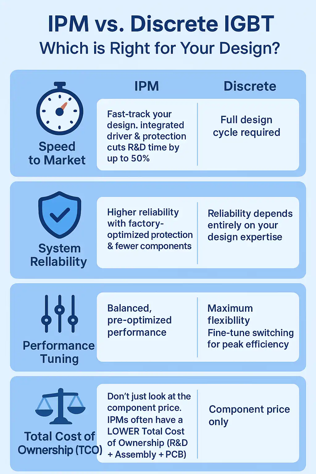
* Title: IPM vs. Discrete IGBT: Which is Right for Your Design?
* Core Concept: A visual guide to help engineers choose between an integrated IPM and a flexible discrete solution based on key project priorities: Speed, Reliability, Performance, and Cost.
* Key Sections & Visuals:
* Point 1: Speed to Market. Icon: A stopwatch or rocket. Text: “IPM: Fast-track your design. Integrated driver & protection cuts R&D time by up to 50%. Discrete: Full design cycle required.”
* Point 2: System Reliability. Icon: A shield. Text: “IPM: Higher reliability with factory-optimized protection & fewer components. Discrete: Reliability depends entirely on your design expertise.”
* Point 3: Performance Tuning. Icon: A tuning knob or equalizer. Text: “Discrete: Maximum flexibility. Fine-tune switching for peak efficiency. IPM: Balanced, pre-optimized performance.”
* Point 4: Total Cost of Ownership (TCO). Icon: A scale balancing a single IPM coin against multiple discrete component + R&D coins. Text: “Don’t just look at the component price. IPMs often have a LOWER Total Cost of Ownership (R&D + Assembly + PCB).”
* Branding: Include Logo: Shunlongwei Co., Ltd. | Website: https://www.slw-ele.com
Related Articles:
- https://www.slw-ele.com/resources/the-core-trio-of-igbt-module-selection-a-practical-guide-to-voltage-current-and-thermal-management
- https://www.slw-ele.com/mastering-igbt-paralleling-a-guide-to-achieving-balanced-current-sharing.html
- https://www.slw-ele.com/ipm-vs-discrete-igbt-a-framework-for-system-cost-and-reliability.html
- https://www.slw-ele.com/from-chip-to-air-a-holistic-approach-to-igbt-thermal-design.html