Content last revised on September 27, 2026
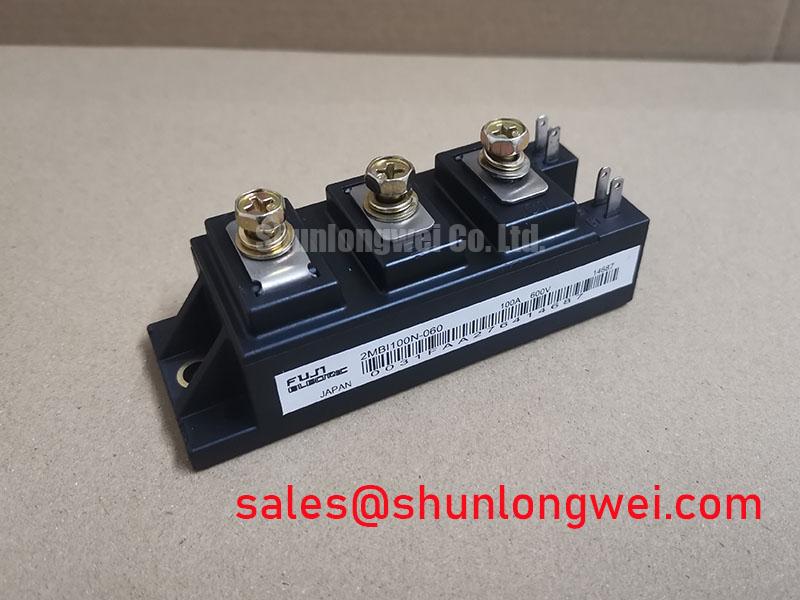
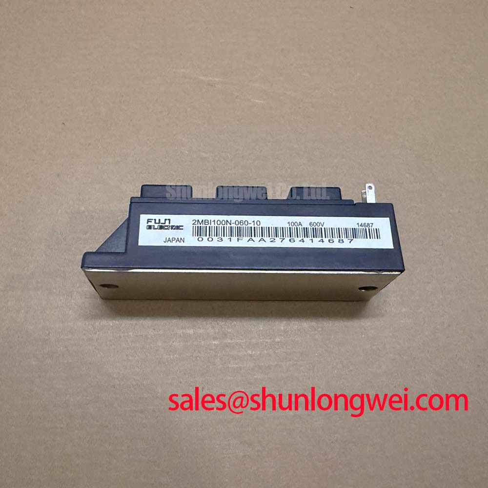
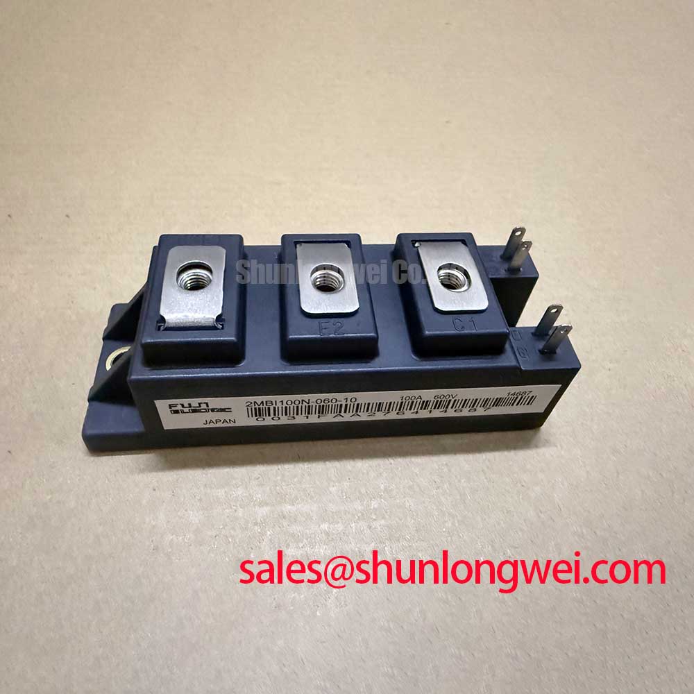
Benchtop Waveform Tuning: Mitigating Stress via PCB Gate Loop Layout Symmetry on 2MBI100N-060-10
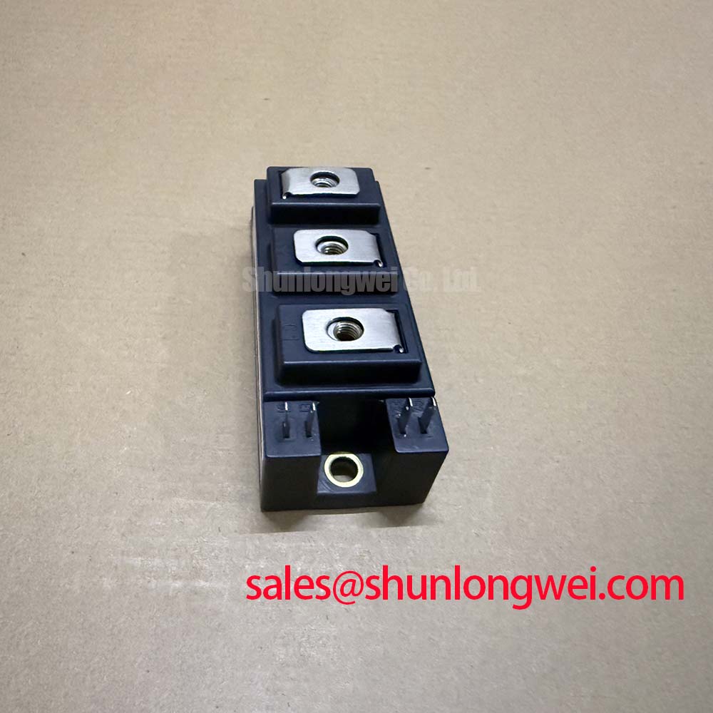
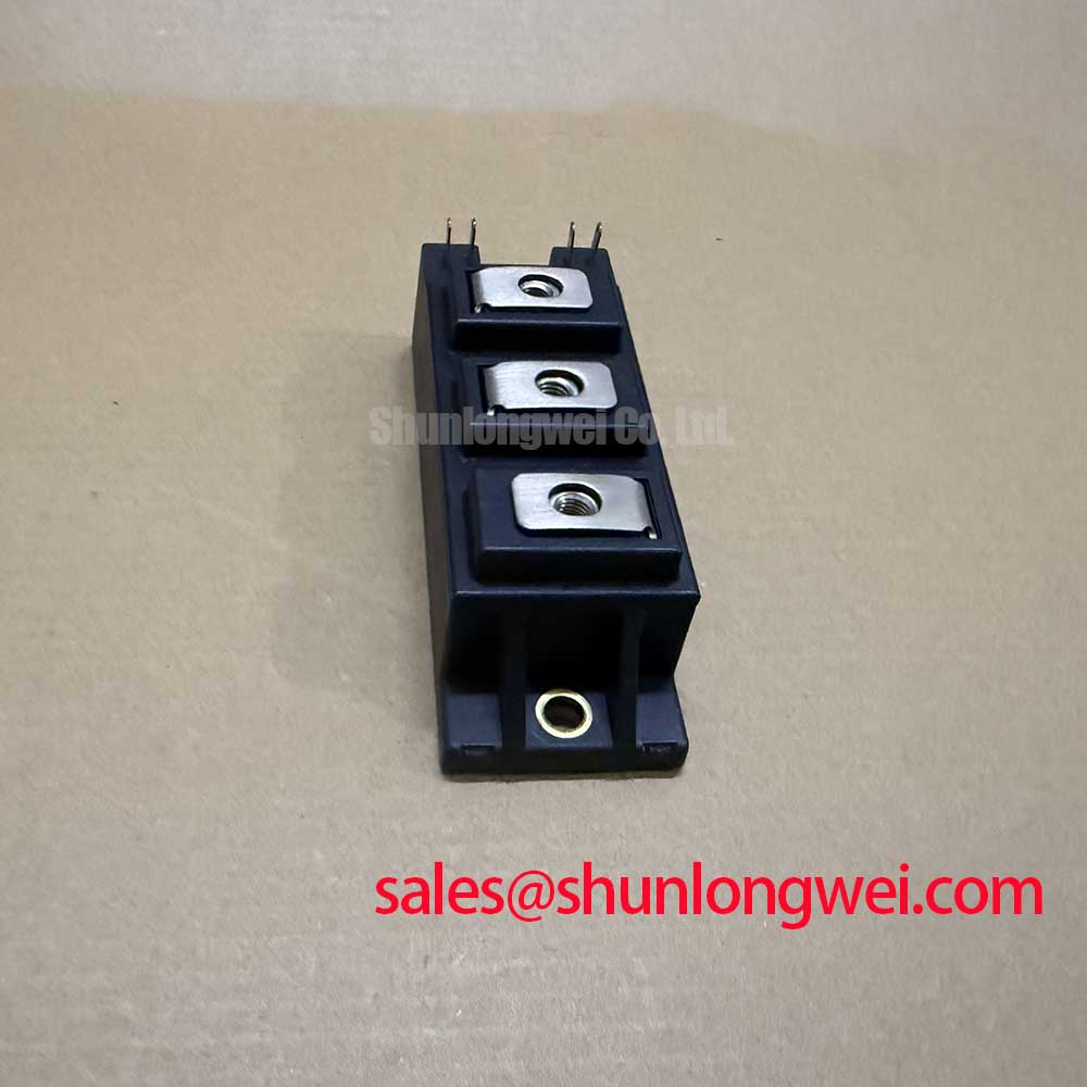
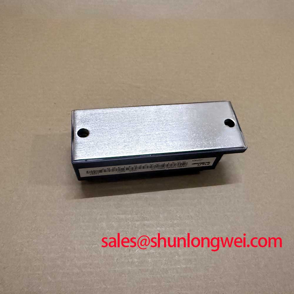
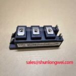
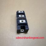
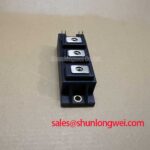
Before connecting the power stage, verify the nameplate rating, inspect the case and terminals, and measure the unpowered resistance between the relevant power terminals against a known-good reference. For the Fuji Electric 2MBI100N-060-10, the official device data identifies a 600 V collector-emitter voltage, a 75 A continuous collector current at Tc = 80°C, a typical 1.9 V diode forward voltage at IE = 100 A, a 10 µs short-circuit withstand time, and an IGBT junction-to-case thermal resistance of 0.48 °C/W. These values are official specification data and should be checked against the original equipment documentation before commissioning.
| Parameter | Official Specification |
|---|---|
| Manufacturer | Fuji Electric |
| Product category | IGBT Module |
| Collector-emitter voltage, VCES | 600 V |
| Continuous collector current, IC | 75 A at Tc = 80°C |
| Diode forward voltage, VF | 1.9 V typical at IE = 100 A |
| Short-circuit withstand time, tsc | 10 µs |
| IGBT junction-to-case thermal resistance | 0.48 °C/W |
Start waveform work with the module disconnected from the full traction load and use the lowest practical test energy. The gate driver return path should be routed as a controlled loop rather than sharing the main high-current emitter path. A shared return can introduce emitter mutual coupling, so the measured gate-emitter voltage may contain switching noise that is not present at the driver output. This can encourage unwanted oscillation, delayed turn-off, or uneven switching between parallel current paths.
Design Consideration: Keep the gate command and its return physically close, maintain symmetry between complementary switching paths, and separate the auxiliary control return from the broad copper used for collector or emitter power current. The exact clearance and conductor geometry must be determined from the PCB stack-up, insulation system, switching voltage, and required creepage distance. They should not be inferred from the module part number alone.
During bench commissioning, monitor the gate-emitter waveform directly at the module terminals with a probe arrangement that minimizes the probe loop. Compare the command waveform during turn-on and turn-off, then inspect the collector-emitter waveform for ringing and overshoot. If the gate waveform changes when the DC-link or motor cable is connected, examine the complete commutation loop rather than assuming a defective gate driver. Check connector pressure, terminal cleanliness, driver supply stability, and the physical position of the return conductor.
The 10 µs official short-circuit withstand time is a protection boundary, not a permission to operate continuously in short circuit. The protection circuit should detect abnormal current and remove the gate command within the system response time required by the equipment design. Designers should verify the complete delay, including sensing, blanking, logic processing, and gate discharge, using a controlled test method.
2MBI100N-060-10 Operational Boundaries: Evaluating Braking Resistors and Chopper Transistor Limits
In an electric forklift or warehouse traction inverter, the braking chopper transfers excess regenerative energy from the DC link into a ballast resistor when the traction motor decelerates. The 2MBI100N-060-10 can be evaluated in this role only after the system engineer confirms the DC-link voltage, braking duty cycle, peak current, thermal path, and pulse-energy requirement. The 600 V VCES rating and 75 A current specification must be treated as device boundaries under their stated conditions, not as a complete braking-resistor design.
The resistor calculation belongs to the equipment-level energy model. It should include vehicle mass, speed change, motor and gearbox efficiency, battery absorption capability, DC-link capacitance, and the expected deceleration profile. Short repetitive braking events can produce a different thermal condition from a single long event. The resistor manufacturer’s pulse-energy and average-power data must be evaluated together with the IGBT switching waveform.
Where a phase-controlled rectifier or front-end converter shares the DC link, line-frequency ripple can affect the braking threshold and instantaneous chopper current. The control engineer should examine the DC-link waveform under charging, traction, and regenerative operation. Harmonic mitigation is a system function; firing-angle control, line impedance, filtering, and the selected converter topology all influence the result. The IGBT module itself should not be represented as independently providing power-quality compliance.
RC snubber selection also depends on the actual commutation loop, device switching speed, busbar geometry, and measured voltage overshoot. An Engineering Recommendation is to tune the snubber from oscilloscope measurements taken at the module terminals, while checking resistor pulse stress and capacitor insulation requirements. A snubber that reduces ringing in a low-energy test may create excessive loss during repeated forklift braking cycles.
Fast semiconductor fuses can provide coordinated fault protection when their clearing characteristics and I²t rating are matched to the power module and DC-link capacitor. This requires the fuse data, prospective fault current, bus impedance, and protection response to be reviewed together. The module’s 10 µs short-circuit withstand specification does not replace fuse coordination or gate-driver desaturation protection.
For a system that includes a separate rectifier or complementary power stage, the 2MBI300U4H-120-50 may be reviewed as a related device in the wider topology. This is a neutral reference for system evaluation, not a substitute recommendation. The integrator should confirm voltage class, terminal arrangement, gate-drive requirements, and thermal characteristics from the applicable documentation.
2MBI100N-060-10 Circuit Protection & Reliability: Assessing High-Altitude Cosmic-Ray-Induced SEB Risk
Single-event burnout, terrestrial neutron exposure, altitude effects, and long-term reliability require application-specific evidence. No FIT rate, SEB probability, operating lifetime, or fixed altitude derating should be assigned to the 2MBI100N-060-10 without an authoritative device reliability source and a defined mission profile. The official parameters supplied for this product specify electrical and thermal limits, but they do not establish a universal cosmic-ray failure rate.
As a Design Consideration, engineers evaluating equipment installed at elevated locations should identify the actual installation altitude, DC-link voltage distribution, switching transient profile, duty cycle, cooling condition, and exposure environment. They should then request suitable manufacturer reliability data or perform a qualified system-level assessment. A generic statement such as “above 2000 m” cannot by itself determine an SEB limit or a safe voltage reduction.
Protection development should begin with measured peak collector-emitter voltage during the fastest and most severe switching event. The busbar, capacitor connection, freewheel diode path, and braking resistor loop should be inspected as one network. Designers should preserve voltage headroom between the measured transient and the official 600 V rating, but the required margin is system-determined and must be validated across temperature, battery state, load current, and production tolerances.
For field diagnostics, isolate the DC link, follow the equipment discharge procedure, and compare gate-to-emitter and collector-to-emitter measurements with a known-good phase. Unexpected low impedance, abnormal leakage, or inconsistent diode behavior may indicate damage, contamination, wiring error, or a measurement setup issue. Repeat the test with suitable isolation and confirm the result before replacing the module.
Environmental reliability also depends on enclosure sealing, condensation control, airflow, dust loading, and maintenance practice. These are installation considerations rather than guaranteed features of the module. ⚠️ Maintenance Note: Record heatsink and terminal-area temperature trends during scheduled service, and correct blocked airflow or deteriorated thermal interface material before the contact temperature rises into an abnormal operating pattern.
The Field Engineer’s Handbook provides a related technical reference for structured testing, failure analysis, and reliability review. It should supplement, not replace, the manufacturer’s data and the original traction inverter service procedure.
Field Diagnostics & Commissioning: High-Frequency Commutation Loop Inductance in 2MBI100N-060-10 Topologies
During commissioning, inspect the physical DC-link loop before changing gate resistance or adding suppression parts. Positive and negative bus conductors should follow a compact, symmetrical route from the DC-link capacitor to the module and back through the freewheel current path. The objective is to minimize parasitic loop inductance so that turn-off current change does not create excessive collector-emitter overshoot.
The governing relationship can be discussed in engineering terms: the voltage peak rises with DC-link voltage and with the product of commutation-loop inductance and current change rate. This makes the measured peak dependent on busbar spacing, capacitor placement, current level, switching speed, probe technique, and load condition. The system designer must verify the peak against the 600 V official rating during switching tests; a fixed inductance target should not be presented as a guaranteed requirement for this module.
Use a properly rated differential probe at the module power terminals and confirm probe bandwidth, grounding, and calibration. A long ground lead can create ringing that is not present in the equipment. Capture turn-off at low, nominal, and maximum expected current, then compare the waveform with the resistor and capacitor network connected. If the ringing frequency changes after a snubber is installed, evaluate both damping performance and additional switching loss.
Snubber capacitors should be selected for voltage stress, pulse current, dielectric behavior, mounting inductance, and repetitive thermal loss. Their capacitance cannot be sized from the 2MBI100N-060-10 part number alone. The resistor must also withstand the pulse energy and average dissipation generated by the switching frequency. Designers should validate the final network under the actual braking and traction duty profile rather than relying only on a static bench waveform.
When a replacement is being considered, mechanical fit, terminal orientation, isolation requirements, gate-drive compatibility, diode behavior, and thermal resistance must all be checked. The 2MBI400TB-060-01 is a related Fuji Electric module that may be reviewed for cross-reference research, but suitability is determined by the original inverter design and documented electrical and mechanical requirements.
For forklift traction service, final commissioning should include controlled acceleration, regenerative braking, DC-link ripple observation, gate waveform inspection, and thermal monitoring. The system integrator should verify that the cooling assembly, electrical clearances, protection timing, and busbar arrangement remain within the equipment design limits before returning the vehicle to duty.