

Content last revised on September 13, 2026
6MBI450U-170 Circuit Protection & Reliability: Calibrating Transient Thermal Impedance
A short overload event cannot be assessed from the continuous current label alone. For the 6MBI450U-170, the field task is to establish whether the original converter’s protection and cooling system still control junction temperature during its actual pulse profile. The relevant transient thermal-impedance curve and thermal network data must be taken from the applicable Fuji Electric documentation for this exact part and revision. Do not substitute a curve from another current class or voltage family, because it can produce a misleading junction-temperature estimate.
As a Design Consideration, engineers commonly evaluate each heating interval by combining measured or calculated conduction and switching loss with the relevant transient thermal response from the manufacturer data, then adding the measured case-temperature condition. The resulting peak junction-temperature assessment must remain within the manufacturer’s stated operating boundary. The pulse duration, repetition pattern, baseplate contact, heatsink temperature, airflow or liquid-flow condition, and previous load history all influence the result. A module that appears acceptable after a brief no-load check can still encounter thermal stress when the converter resumes real torque or power demand.
During a shutdown investigation, inspect the mounting plane for trapped debris, uneven thermal-interface transfer, corrosion products, and signs that the module has not been held uniformly against the heatsink. Confirm that temperature sensors, fan feedback, coolant interlocks, and overtemperature logic are working before treating the module itself as the only suspect. A rapid case-temperature rise may reflect an impaired thermal path or an abnormal switching condition; it does not prove one particular internal failure mechanism.
⚠️ Field Alert: Tighten mounting hardware according to the equipment maker’s fastener specification and apply the thermal interface evenly, because uneven clamping can distort thermal measurements and local heat transfer.
For protection coordination, the system integrator should review the semiconductor fuse documentation, controller trip timing, current-sensor validity, and the converter manufacturer’s specified fault-clearing sequence. The 450.0 A rating is not a substitute for a verified short-circuit protection strategy. Where surge-current capability or fault withstand is needed, use only the exact manufacturer ratings and test conditions applicable to this module rather than extrapolating from nominal current.
Assembly Integrity & Layout Architecture: Implementing Planar Symmetrical Busbar Geometry for 6MBI450U-170
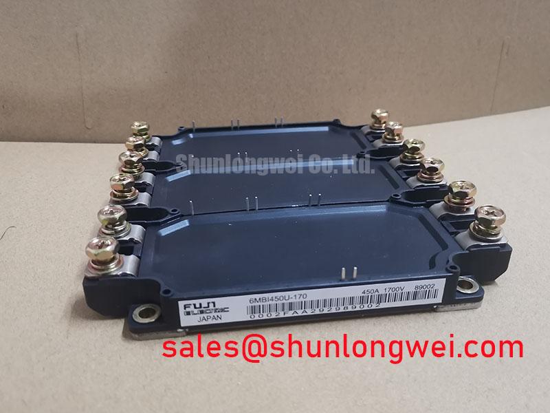
Before fitting a replacement module, photograph the busbar stack, terminal hardware, gate harness routing, snubber connections, and any insulating barriers in their original positions. The physical package is specified as a Module, but terminal arrangement, mounting footprint, connection sequence, and auxiliary-terminal functions must be verified against the original equipment documentation. A mechanically similar assembly is not evidence of electrical interchangeability.
Design Consideration: the turn-off peak voltage is influenced by DC-bus voltage plus the product of stray inductance and current-change rate. This relationship explains why physical assembly matters during repair. Keep the commutation loop compact, use paired conductor paths where the original design does so, and restore the original symmetrical busbar geometry as closely as practical. These measures help suppress inductive overshoot, but the system engineer must verify peak voltage margins with properly rated differential measurement during switching tests.
Freewheeling behavior can also affect ringing and radiated disturbance. If waveform capture shows a sharp recovery transition, repeated oscillation, or unequal behavior between otherwise comparable phases, inspect the local DC-link capacitor connection, snubber condition, busbar contact pressure, and driver-loop return path. The correct snubber capacitance and damping arrangement are system-determined values; they must be retained from the converter design or validated through controlled measurement. Changing components to an assumed value can move the stress rather than eliminate it.
For a related power-stage assessment, the 2MBI400U4H-170 can be reviewed as a separate device record when the upstream rectifier or auxiliary conversion section requires identification. It should not be treated as a prescribed substitute for the 6MBI450U-170. Confirm electrical function, circuit location, mounting interface, control arrangement, and the original equipment schematic before any replacement decision.
Fuji Electric’s Brake Chopper IGBT Modules information is useful background when identifying power-semiconductor roles in braking and energy-management circuits. It does not establish the topology, application rating, or interchangeability of this specific module in a particular converter.
6MBI450U-170 Operational Boundaries: Evaluating Thermal Feedback Limits
After installation, compare phase-current behavior, gate commands, and heatsink response under a controlled recommissioning procedure defined by the equipment owner. In parallel paths, steady-state current distribution can be influenced by the temperature dependence of on-state voltage, while switching distribution depends heavily on matched gate-loop resistance, wiring length, driver timing, and parasitic inductance. Design Consideration: restore each gate and emitter return connection to its original symmetrical routing and inspect for loose crimping, damaged insulation, or altered harness length.
A mismatch seen on an oscilloscope may indicate gate-drive asymmetry, sensor scaling, busbar coupling, controller timing, measurement setup, or a power-stage issue. Verify the observation against a known-good signal path and use probes with an appropriate voltage and bandwidth rating. Avoid judging semiconductor health from a single switching capture taken under an unknown load condition. The repair record is more useful when it captures the DC-link condition, current command, temperature state, probe locations, and controller operating mode.
For wind-turbine full-scale converter evaluations, the module can be considered within the repair review of a multi-megawatt onshore or offshore system only after the original electrical and mechanical interfaces are matched. Such equipment can experience changing ambient conditions, variable load spectra, and repeated thermal cycling, but no operating-life figure or field failure rate should be inferred without validated system evidence. The converter manufacturer’s maintenance instructions and recorded operating conditions remain the basis for service decisions.
Where a nearby assembly uses the same product family, 6MBI450U-120A-05 is available as a neutral reference point for part-number comparison. Engineers should compare the complete official documentation, including ratings, package interface, terminal layout, circuit function, and drive requirements. A shared naming pattern or apparent dimensional similarity does not establish a direct replacement path.
Transient Dynamics & Electrical Design: DC-Bus Operating Voltage Headroom Derating on 6MBI450U-170
The 1700.0 V official voltage rating must be checked against the complete measured switching environment, not only the nominal DC-bus value displayed by the controller. At recommissioning, capture voltage at the module-side power loop where safe measurement practice permits, then compare transient peaks, ringing, and repetition behavior with the equipment maker’s electrical limits. Design Consideration: minimize parasitic loop inductance to reduce turn-off overshoot, and let the system engineer determine acceptable headroom through tested peak-margin verification.
Altitude, environmental conditions, and cosmic-radiation-related semiconductor effects require application-specific evaluation. No quantified single-event burnout rate, failure-in-time figure, altitude threshold, lifetime, or derating factor is stated here because such values require authoritative manufacturer data or a documented qualification source for the exact operating conditions. For a site above the converter maker’s stated environmental envelope, the responsible system engineer should obtain the applicable equipment and semiconductor guidance before returning the installation to service.
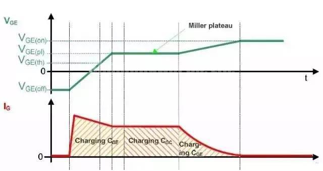
Gate-drive integrity remains central to transient control. Check that the driver supply, isolation arrangement, desaturation or overcurrent protection path, gate connection polarity, and fault-reset behavior agree with the original converter schematic. The Miller region and gate-to-collector coupling can contribute to unintended gate movement during fast voltage transitions, so active clamping or other protective features must be assessed as part of the existing driver design, not added on assumption. Practical measurement methods and gate-loop review points are discussed in Precision Gate Drive Design for engineers preparing a controlled troubleshooting plan.
Before releasing the equipment, verify terminal torque against the converter manufacturer’s service instructions, confirm protective covers and clearances are restored, and perform the prescribed insulation and functional checks at the system level. The module’s declared 1700.0 V and 450.0 A ratings identify its official electrical boundary; safe operation depends on the complete converter assembly, its protection response, and measured behavior under its intended duty.