


Content last revised on April 26, 2026
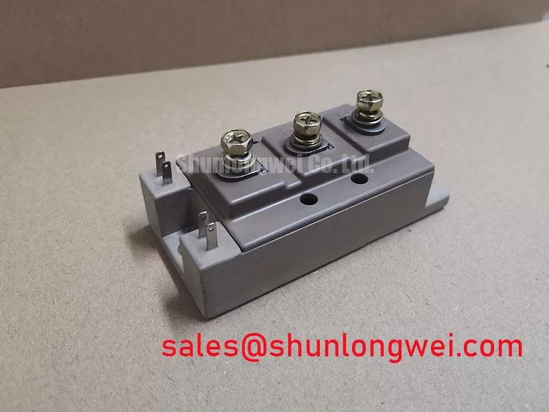
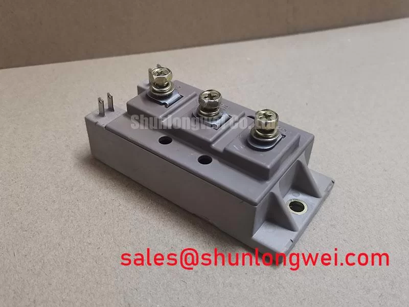
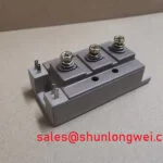
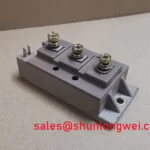
2MBI150UM-120-50 Fuji Electric IGBT Module: Engineering for High-Speed Power Conversion
An In-Depth Analysis of a 1200V, 150A Dual IGBT Module
Key Parameter Overview
Decoding the Specs for Enhanced Switching Performance
The 2MBI150UM-120-50 is an N-channel dual IGBT module from Fuji Electric's V-Series, engineered for demanding power conversion applications. Its electrical characteristics are optimized for designs that require a balance between low conduction losses and fast switching speeds. A low Collector-Emitter Saturation Voltage (VCE(sat)) is crucial for minimizing power dissipation during the on-state. To visualize this, think of VCE(sat) as the "friction" the current encounters when the switch is closed; a lower value means less energy is wasted as heat, directly improving the overall efficiency of the system. This allows for either higher output power at the same temperature or a reduction in the required cooling hardware, impacting system size and cost.
The module's performance is defined by a careful balance of static and dynamic parameters. Understanding these specifications is the first step toward leveraging its full capabilities in your power stage design.
| Parameter | Symbol | Test Conditions | Value |
|---|---|---|---|
| Absolute Maximum Ratings (at Tc=25°C unless otherwise specified) | |||
| Collector-Emitter Voltage | VCES | - | 1200V |
| Gate-Emitter Voltage | VGES | - | ±20V |
| Continuous Collector Current | IC | Tc=80°C | 150A |
| Pulsed Collector Current | ICP | - | 300A |
| Collector Power Dissipation (per device) | PC | - | 1070W |
| Operating Junction Temperature | Tj | - | +175°C |
| Isolation Voltage | Viso | AC, 1 minute | 2500V |
| Electrical Characteristics (at Tj=25°C unless otherwise specified) | |||
| Collector-Emitter Saturation Voltage | VCE(sat) | VGE=15V, IC=150A | 1.9V (typ.), 2.4V (max.) |
| Gate-Emitter Threshold Voltage | VGE(th) | VCE=20V, IC=150mA | 6.0V (typ.) |
| Turn-on Time | ton | VCC=600V, IC=150A, RG=1.1Ω | 380ns (typ.) |
| Turn-off Time | toff | 600ns (typ.) | |
Note: The parameters listed are based on the Fuji Electric V-Series datasheet for the related 2MBI150VA-120-50 model, which shares the core ratings. These values are for reference and should be verified against the official documentation for the specific model number.
Application Scenarios & Value
Achieving System-Level Benefits in Motor Drives and Power Supplies
The 2MBI150UM-120-50 is engineered for high-frequency power conversion systems where efficiency is paramount. Its primary applications include inverters for motor drives, AC and DC servo drive amplifiers, and uninterruptible power supplies (UPS). For designers of Variable Frequency Drives (VFDs), the challenge is often to reduce motor noise and improve torque control by increasing the switching frequency. However, higher frequencies lead to greater switching losses. The 2MBI150UM-120-50 addresses this directly with its optimized turn-on (ton) and turn-off (toff) times. These fast switching characteristics reduce the time the device spends in the high-dissipation transition state, effectively lowering total switching losses and enabling more efficient operation at higher frequencies. This translates to smaller, lighter, and more cost-effective magnetic components and heatsinks within the VFD system. For systems requiring slightly more current handling capability, the related 2MBI200NB-120 offers a higher current rating within a similar voltage class.
Frequently Asked Questions (FAQ)
What is the primary benefit of the typical 1.9V VCE(sat) at the rated 150A current?
A lower VCE(sat) directly reduces conduction losses (P = VCE(sat) * IC), which is the dominant form of power loss in applications with high duty cycles. This results in less heat generation, improving overall system efficiency and thermal stability, potentially allowing for a smaller heatsink design and higher power density.
How do the ton and toff times of 380ns and 600ns, respectively, influence application design?
These high-speed switching parameters are critical for minimizing switching losses, especially in systems operating at higher frequencies such as modern motor drives or high-power switch-mode power supplies. Faster switching reduces the time the IGBT spends transitioning between on and off states, where power dissipation is highest. This efficiency gain allows designers to increase the operating frequency to reduce the size of passive components like inductors and capacitors, or to simply achieve higher efficiency at a given frequency.