

Content last revised on September 10, 2026
7MBP75RA120-55 Product Identification and Initial Inspection
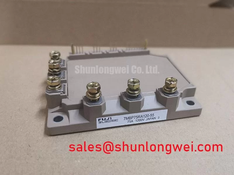
Before connecting the DC bus or gate-drive harness, verify the module marking, inspect the terminal insulation surfaces, and compare cold-state resistance readings between power terminals with a known-good assembly where available. The 7MBP75RA120-55 is a Fuji Electric power module rated at 1200 V and 75 A under its official datasheet conditions. Its product form is a module; the original equipment documentation remains the controlling reference for terminal assignment, driver interface, protection thresholds, and mechanical installation details.
| Item | Official Specification |
|---|---|
| Product model | 7MBP75RA120-55 |
| Manufacturer | Fuji Electric |
| Rated voltage | 1200 V |
| Rated current | 75 A |
| Product category | Power module |
Maintenance teams assessing an industrial inverter welder or a medium-frequency induction-heating supply should treat the 1200 V and 75 A ratings as component boundaries, not as complete system ratings. DC-link voltage, switching waveform, cooling performance, fault response, and the existing gate-drive board all affect the installed operating condition. Fuji Electric’s Power Semiconductor and IPM Modules information provides useful manufacturer context when identifying the power-stage family used in an existing cabinet.
Benchtop Waveform Tuning: Mitigating Stress via Kelvin Emitter Connection on 7MBP75RA120-55
When a replacement 7MBP75RA120-55 is being installed, begin with the original schematic and terminal drawing rather than assuming that every auxiliary terminal has the same function across power-module families. If the documented interface provides a dedicated emitter sense or auxiliary emitter return, it should be routed separately from the main high-current emitter path as a design consideration. This separation helps prevent shared power-loop voltage from being imposed on the gate-drive reference during rapid current transitions.
On a service bench, inspect the driver cable routing, connector engagement, and return-path continuity before energizing the main DC link. A gate waveform that appears noisy or inconsistent can arise from several interacting conditions, including an unsuitable return path, connector contact degradation, excessive lead length, or a driver fault. Use an appropriately rated differential measurement method and compare the gate-to-emitter waveform with the documented driver behavior. Do not infer a gate-drive setting from the module’s voltage and current ratings alone.
Keep gate-drive conductors away from high-current busbar edges and switching nodes where practical. This is an engineering recommendation based on controlling coupling into the low-level drive loop. Clearance and creepage distances must be verified against the equipment insulation design, contamination conditions, enclosure construction, and applicable system standard. For systems that need a structured review of driver-loop behavior, the Precision Gate Drive Design guide can support a discussion with the responsible power-electronics engineer.
⚠️ Maintenance Note: Isolate and discharge the equipment according to its approved procedure before reconnecting any gate-drive or DC-bus cable.
7MBP75RA120-55 Circuit Protection & Reliability: Calibrating DC-Bus Low-Inductance Laminated Busbar Design
Turn-off overvoltage is governed by the DC-link voltage plus the voltage developed across stray loop inductance as current changes. In practical terms, reducing the physical loop area between the DC-link capacitor, busbar, and power-module terminals helps suppress inductive overshoot. This is a design consideration, not an official inductance specification for the 7MBP75RA120-55.
For an inverter welder or induction-heating power supply, inspect whether the outgoing and return bus conductors are tightly coupled through the complete commutation path. Laminated or closely paired planar conductors are often evaluated because symmetrical routing can reduce loop inductance and improve switching repeatability. The system engineer should validate peak terminal voltage against the DC-link voltage during switching tests, using the actual switching current, temperature, load condition, and protective-clamp response.
Snubber film capacitors and MOV-based suppression networks should be assessed as parts of the existing equipment protection architecture. Their placement, interconnection length, capacitor current capability, and coordination with the control-board fault response are system-determined. A snubber placed electrically distant from the switching loop may not provide the intended transient control. During fault investigation, inspect capacitor terminals, busbar fasteners, insulation barriers, and signs of localized heating, then correlate physical findings with captured switching waveforms before changing parts.
Where a lower-current module family is under objective compatibility review, 7MBR35UA120 provides a related reference point for comparing documented electrical ratings and package interfaces. Mechanical fit, driver compatibility, protection coordination, and thermal conditions must be checked from the respective original documentation before any substitution decision.
7MBP75RA120-55 Thermal-Electrical Optimization: Baseplate Convexity Compensation and Screw Practical Tuning
Before mounting the module, clean the heatsink contact area and inspect it for corrosion, raised burrs, trapped debris, or uneven residue from aged thermal interface material. The flatness of both mating surfaces matters because a localized gap can increase thermal resistance and create uneven temperature distribution. The 7MBP75RA120-55 should be mounted only with the hardware arrangement and tightening sequence specified by the original module documentation or equipment manufacturer.
Thermal grease or another approved interface material should be applied as a thin, continuous layer that fills surface irregularities without creating excessive thickness or trapped air. This is a design consideration; the correct material, layer control, and mounting hardware depend on the equipment design. If the baseplate or heatsink surface shows visible distortion, treat it as a mechanical service issue rather than compensating solely by adding more interface material.
Use a gradual cross-pattern tightening sequence where the original mounting layout supports it, then verify that terminal hardware is secure according to the equipment’s approved torque requirement. Uneven screw loading can affect interface contact and may also place unnecessary stress on the module housing. During preventative maintenance, monitor heatsink cleanliness, fan operation, airflow restrictions, thermal-material condition, and terminal contact temperature trends. A temperature rise at one connection may indicate several conditions, so inspect conductor condition and clamping integrity before assigning a cause.
Fuji Electric identifies PIM products within its PIM 7-Pack product information. For equipment repair, use the cabinet wiring diagram and module-specific documentation to verify the installed topology and cooling arrangement rather than relying on family-level construction assumptions.
Benchtop Waveform Tuning: Mitigating Stress via Cosmic Ray Robustness and Voltage Derating Considerations on 7MBP75RA120-55
The official datasheet specification supplied for this page confirms 1200 V rated voltage and 75 A rated current, but it does not establish a specific cosmic-ray, single-event burnout, altitude, or FIT-rate claim for this product page. Such matters must not be converted into a numerical lifetime or failure-rate prediction without a directly applicable manufacturer qualification source and defined operating conditions.
For installations at elevated locations or in unusually demanding electrical environments, treat environmental robustness as a system-level design consideration. The equipment designer should review the actual DC-link operating range, switching transients, surge environment, cooling behavior, enclosure condensation control, and protection response. Verification should be performed against the relevant equipment requirements and the original Fuji Electric documentation.
In maintenance work, prevent condensation exposure by keeping the cabinet sealed as intended, restoring damaged gaskets and cable entries, and confirming that cooling airflow does not pull excessive dust into the power compartment. Inspect for moisture residue near busbar insulation, gate-drive connectors, and control-board interfaces. These steps do not establish an altitude or radiation qualification; they provide practical evidence for deciding whether the power stage and its surrounding assembly require further engineering evaluation.