

Content last revised on September 10, 2026
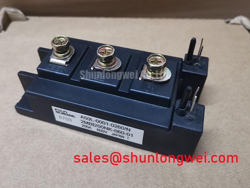
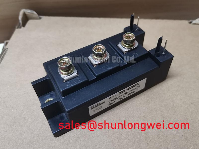
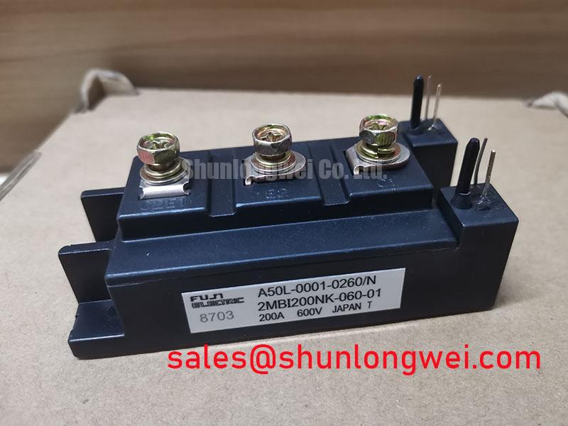
Assembly Integrity & Layout Architecture: Implementing DC Bus Operating Voltage Headroom Derating for 2MBI200NK-060-01
Begin the installation review at the DC bus, because bus voltage excursions, conductor routing, and switching loop geometry determine what the fitted module experiences in the actual inverter. The specified 600 V voltage rating does not establish the allowable DC link voltage for a particular inverter welder or medium frequency induction heating power supply. That boundary must be confirmed from the original Fuji Electric documentation and the equipment circuit design.
DC bus voltage headroom is a Design Consideration. Engineers should account for supply variation, regenerative energy, transformer leakage effects, and turn off overshoot rather than relying on nominal bus readings. Keep high current bus conductors short, paired, and mechanically secure so that stray inductance does not add unnecessary voltage stress during switching. Clearance and creepage distances should follow the original equipment insulation design and the applicable installation standard, especially where contamination, condensation, or conductive process dust is possible.
Altitude, terrestrial neutron flux, single event burnout, and failure in time calculations require device specific qualification data and a defined operating environment. No quantified altitude derating, neutron related failure rate, or single event burnout conclusion should be assigned to this module without an authoritative Fuji Electric source and a system level assessment. For equipment used outside its established installation envelope, a practical evaluation includes recording the DC link waveform, checking peak voltage at the module terminals, and reviewing fault logs under representative load transitions.
💡 Pro Tip: Use a symmetrical laminated bus arrangement where the assembly permits it, then confirm switching peak margins with controlled double pulse measurements rather than assuming that a compact physical layout is electrically low inductance.
For broader context on high voltage switching margins and test discipline, maintenance teams can consult Wide Bandgap Revolution as a technical reference while retaining the original IGBT module requirements for this repair.
Assembly Integrity & Layout Architecture: Implementing Thermal Time Constants and Peak Junction for 2MBI200NK-060-01
Heavy pulsed welding and induction heating duty can produce a thermal response that is not visible from a steady state heatsink reading. Peak junction assessment is therefore a Design Consideration based on the applicable transient thermal impedance curves, load pulse profile, switching loss, conduction loss, case temperature, and cooling performance. A multi RC thermal model can represent the time dependent path from junction to case, but its inputs must come from the relevant manufacturer data and measured converter operating conditions.
During commissioning, capture pulse current, switching waveforms, DC bus behaviour, cooling inlet conditions, and case temperature through the intended work cycle. Compare those observations with the permitted limits documented for the original power stage. A rising case temperature can indicate restricted coolant flow, uneven heatsink contact, aged interface material, or an altered switching condition; it does not by itself identify one root cause.
The module base and heatsink should be clean, flat, and free from burrs before assembly. Thermal interface material should be applied as specified by the equipment manufacturer, with fasteners tightened in the documented sequence to avoid uneven mechanical loading. Mounting torque is a General Industry Design Consideration and must not be treated as an official value for this specific part unless confirmed by Fuji Electric documentation.
Place the local film capacitor and suppression network according to the existing power stage layout so the commutation loop remains compact. This is an Engineering Recommendation to reduce inductive turn off stress. Any change to snubber capacitance, resistor value, busbar arrangement, or cooling hardware should be validated by waveform measurement and thermal testing under the actual duty cycle.
Field Diagnostics & Commissioning: Sizing Braking Resistors and Chopper Trans in 2MBI200NK-060-01 Topologies
In regenerative power stages, braking components convert returned mechanical or magnetic energy into heat when the DC link rises during deceleration or load release. The braking transistor, resistor assembly, control threshold, airflow path, and protective logic form a system function. Their values cannot be derived from the 200 A module current rating alone.
For an inverter welder, inspect whether the DC link is affected by transformer energy, output inductor energy, or programmed current decay. In medium frequency induction heating equipment, evaluate the resonant tank, rectifier section, and commanded power transition. Designers should determine resistor energy capability from the measured regenerative event, repetition rate, permitted resistor temperature, and controller response. The system engineer must then validate the result under abnormal but controlled operating conditions.
Field diagnostics should start with de energised continuity checks of the resistor path, gate drive connector, bus joints, and thermal cutout circuit. After the safety interlock review, observe the DC bus and braking command with properly rated instrumentation. A bus rise with no expected brake command may indicate a control, sensing, wiring, or power stage issue. A brake command with unusual bus behaviour may indicate a separate issue in the resistor path, transistor path, or measurement reference. Test against a known good waveform where available.
The wider converter chain can also contain modules with different functional roles. For example, 2MBI400TB-060-01 can be reviewed as an associated module for topology comparison, but electrical compatibility, terminal geometry, drive requirements, and thermal design must be verified from the equipment documentation before any substitution decision.
2MBI200NK-060-01 Thermal Electrical Optimization: Dynamic Gate Impedance Control for Robust Practical Tuning
Gate drive behaviour should be assessed at the installed module terminals, not only at the controller output connector. Long gate conductors, shared emitter return paths, and poorly controlled power loop geometry can couple switching transients into the gate circuit. The resulting disturbance may contribute to unintended turn on, irregular switching loss, or excessive stress, depending on the complete converter layout.
Active Miller clamping and negative gate bias are Design Considerations, not confirmed factory requirements for 2MBI200NK-060-01. Their suitability depends on the original driver design, isolation arrangement, gate threshold characteristics, switching frequency, common mode transient behaviour, and protection timing. When integrating a replacement module, engineers should retain the established drive architecture unless the complete gate loop is being requalified with controlled measurements.
Check gate to emitter waveforms during turn on, turn off, short circuit protection response, and the highest intended load transition. Review whether the driver has a dedicated return reference, whether desaturation protection remains correctly connected, and whether the gate resistor network is intact. Any adjustment to dynamic gate impedance should be treated as a Typical Starting Point only after the system engineer defines the test conditions and verifies voltage overshoot, current behaviour, switching loss, and thermal margin.
For repair teams comparing original equipment materials, 2MBI200UR-120-01 is an available related module page for objective specification review. It should not be assumed interchangeable with this Fuji Electric module without confirming the circuit function, ratings, package interface, gate drive behaviour, and cooling arrangement.
Fuji Electric publishes product family context for braking applications through its Brake Chopper IGBT Modules resource. That reference can support topology review, while the installed equipment documentation remains the controlling source for the exact operating limits of this module.