


Content last revised on September 24, 2026
6MBI225-120A-05 Thermal Electrical Optimization for Pulsed Operation
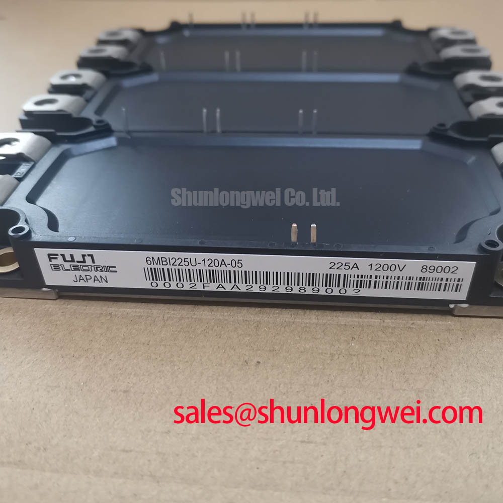
Begin service work by isolating the equipment, recording the module marking, checking the external terminals for contamination, and verifying the rating data against the original Fuji Electric documentation before applying power. The Fuji Electric 6MBI225-120A-05 is an IGBT module with a specified voltage rating of 1200 V and a rated current of 225 A. These values should still be confirmed against the applicable manufacturer datasheet and the conditions associated with each rating.
For an industrial inverter welder or medium frequency induction heating supply, thermal assessment should follow the actual switching waveform and load duty rather than relying only on average current. A transient thermal network can represent the junction to case response with several RC stages, allowing the maintenance engineer to compare the calculated junction temperature rise during each pulse with the permitted device limit stated in the verified Fuji Electric documentation. The thermal model should include pulse width, repetition rate, case temperature, cooling airflow, and the measured interface condition.
When a module runs hotter after a service intervention, inspect the heatsink contact surface, thermal interface material, fan path, and clamping condition before changing gate drive settings. A thermal camera can help locate uneven heating, while thermocouple measurements at the case provide a useful cross check. Any overload or short circuit event should also be reviewed against the semiconductor fuse coordination and the available I²t data. Fuse selection remains a system protection decision and must be verified against the complete inverter topology and the manufacturer’s short circuit limits.
The Fuji Electric reference page for brake chopper IGBT modules provides relevant manufacturer context for power switching applications. It should not be treated as a substitute for the exact datasheet of this model.
Benchtop Waveform Tuning for Low Inductance DC Bus Integration
Before connecting a replacement module to a live DC bus, inspect the commutation loop and measure switching behavior with suitable differential voltage and current probes. Stray inductance in the busbar, capacitor connection, emitter path, and gate loop can produce turn off overshoot. The relationship between peak switch voltage, DC bus voltage, stray inductance, and current slew rate is useful as an engineering calculation, but the acceptable peak must be established from the verified device rating and the tested system margin.
Use a compact, symmetrical bus structure where practical, keeping the high di/dt loop short and avoiding unnecessary conductor overlap that increases loop area. Snubber selection should be based on measured ringing energy, switching frequency, capacitor pulse capability, and resistor dissipation. A starting value copied from another inverter is not a reliable substitute for oscilloscope verification.
Gate loop routing deserves the same attention. Keep the drive and return conductors close together, separate power commutation paths from sensitive control wiring, and evaluate both turn on and turn off waveforms. External gate resistance is a tuning component rather than a fixed guarantee for this model. Designers should adjust it only after confirming driver source and sink capability, gate voltage behavior, switching loss, and ringing at the module terminals.
⚠️ Maintenance Note: Disconnect and verify the DC bus is discharged before removing gate wiring, power terminals, or the module from the heatsink.
Assembly Integrity and Heatsink Contact Architecture
Clean the mounting base and heatsink with a suitable process that does not leave conductive residue. The contact surface should be flat, free from burrs, and free from particles that can create local pressure points. Apply the thermal interface material evenly according to its manufacturer’s instructions; its final thickness and spread pattern are system assembly variables, not confirmed factory parameters for this module.
Use a staged tightening sequence so the package seats progressively rather than being pulled down from one corner. The correct fastener type, washer arrangement, and torque must come from the verified Fuji Electric mechanical drawing or the equipment service manual. Do not transfer a torque value from a different package without checking thread size, baseplate construction, and heatsink design.
After assembly, inspect for rocking, visible interface displacement, and uneven contact marks. Measure case temperature at comparable load points before and after service. A rising thermal gradient may indicate airflow restriction, interface deterioration, mechanical distortion, or an electrical imbalance, so the investigation should compare thermal, electrical, and mechanical evidence rather than assign a single cause.
For replacement planning, engineers may evaluate the linked 6MBI450U-120A-05 as a separate catalogue item, but electrical, mechanical, gate drive, and protection compatibility must be confirmed by the system designer before any substitution.
Isolation and Common Mode Transient Evaluation
Gate driver isolation, creepage, clearance, connector routing, and shield termination should be reviewed together when this module is integrated into a welder or induction heating power stage. The supplied product information does not establish a reinforced isolation rating or a common mode transient immunity rating for the exact model. Those values must be obtained from the relevant driver and module documentation rather than inferred from the package name.
During bench testing, monitor the gate to emitter waveform at the module terminals while applying the highest representative switching transition. Look for unexpected gate movement, delayed turn off, asymmetry between parallel paths, or control disturbances that coincide with bus commutation. Verify probe reference integrity before interpreting a narrow pulse as a real gate event.
Isolation coordination should account for pollution, condensation, enclosure layout, and the actual working voltage. Industrial equipment exposed to temperature cycling should be inspected for moisture deposits and connector contamination during scheduled service. Designers should verify the complete insulation system through applicable equipment-level testing and document the result for the final assembly.
Long-term inspection records, measured thermal trends, waveform captures, and protection test results can be organized with the Field Engineer’s Handbook. The handbook supports maintenance analysis, while the exact Fuji Electric datasheet remains the controlling source for model-specific electrical, thermal, mechanical, and isolation limits.