


Content last revised on June 16, 2026
6MBP30RH060 Fuji Electric IPM: Technical Analysis for Motor Drive Reliability
An Engineer's Overview of the 6MBP30RH060 Intelligent Power Module
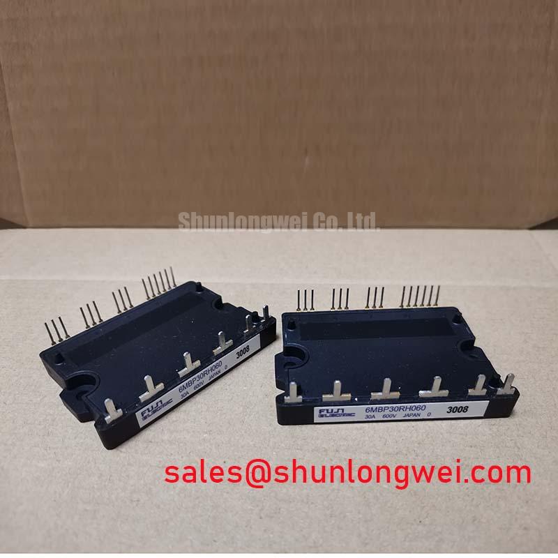
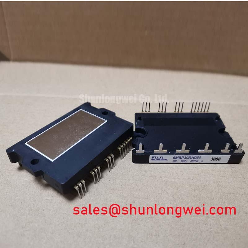
The Fuji Electric 6MBP30RH060 is an intelligent power module (IPM) engineered to maximize the reliability and simplify the design of low-power motor drives through comprehensive, built-in protection and a direct MCU interface. This device integrates a full three-phase inverter power stage with critical control and protection circuits into a single, compact package. Key specifications include: 600V | 30A | Integrated OC, SC, UV & OT Protection. The primary engineering benefits are significantly enhanced system robustness and a dramatically simplified design cycle. It directly answers the need for a protected, easy-to-implement power stage without the complexity of discrete component design. For compact motor drives up to 2.2kW requiring high operational reliability, this IPM offers a highly integrated and protected power stage solution.
Application Scenarios & Value
System-Level Benefits in Compact Motor Control Applications
The 6MBP30RH060 is engineered for high-performance, compact motor control systems where reliability is a critical design parameter. It is an ideal fit for applications such as industrial automation, HVAC systems, pump controllers, and high-end home appliances. What is the primary benefit of its integrated design? It provides a robust power stage that drastically reduces PCB space and assembly complexity compared to a discrete solution using separate gate drivers, protection circuits, and IGBTs.
Consider the engineering challenge of designing a variable frequency drive (VFD) for a small industrial conveyor system. The motor is subject to frequent start/stop cycles and potential stalls, which can create severe overcurrent or short-circuit events. In a discrete design, this requires carefully selected external sensors, comparators, and a fast-acting logic circuit to protect the IGBTs. The 6MBP30RH060 solves this challenge internally. Its built-in short-circuit (SC) and overcurrent (OC) protection mechanisms constantly monitor the state of the power switches. If a fault is detected, the module's internal gate drive intelligently shuts down the IGBTs in a controlled manner to prevent catastrophic failure, while simultaneously issuing an alarm signal (Fo) to the main system microcontroller (MCU). This built-in intelligence ensures a level of protection and reaction speed that is difficult and costly to achieve with external circuits, directly enhancing the VFD's field reliability.
While the 6MBP30RH060 is optimized for 200-240V AC line applications, systems operating on 400V AC lines could utilize modules with higher voltage ratings such as the 6MBP50RS120.
Key Parameter Overview
Key Electrical and Thermal Specifications for System Design
The following parameters are critical for system integration, thermal management, and performance evaluation. The values presented are based on the official manufacturer's datasheet and represent the core electrical and thermal DNA of the 6MBP30RH060.
| Parameter | Symbol | Value | Conditions |
|---|---|---|---|
| Absolute Maximum Ratings | |||
| Collector-Emitter Voltage | VCES | 600V | |
| Collector Current (DC) | IC | 30A | TC=25°C |
| Collector Current (Pulse) | ICP | 60A | TC=25°C, 1ms pulse |
| Operating Junction Temperature | Tj | -20 to +150°C | |
| Electrical Characteristics (Inverter Part) | |||
| Collector-Emitter Saturation Voltage | VCE(sat) | 2.2V (Typ) / 2.7V (Max) | IC=30A, VCC=15V |
| Forward Voltage (FWD) | VF | 2.0V (Typ) / 2.5V (Max) | IC=30A, VCC=15V |
| Over Current Protection Level | OC | 45A (Typ) | |
| Thermal Characteristics | |||
| Thermal Resistance (IGBT) | Rth(j-c) | 3.0 °C/W | Junction to Case |
| Thermal Resistance (FWD) | Rth(j-c) | 4.5 °C/W | Junction to Case |
Download the 6MBP30RH060 datasheet for detailed specifications and performance curves.
Frequently Asked Questions
Engineering Questions on Implementation and Reliability
What is the function of the Fo (Alarm) pin and how should it be handled in a design?
The Fo pin is an open-collector fault output that serves as a critical diagnostic signal to the host microcontroller (MCU). Under normal operation, this pin is in a high-impedance state. When any of the module's internal protections are triggered—including overcurrent (OC), short-circuit (SC), control supply under-voltage (UV), or over-temperature (OT)—the Fo pin is pulled low. In a robust design, this pin should be connected to an interrupt input on the MCU via a pull-up resistor. This allows the system to immediately cease sending PWM signals and initiate a safe shutdown procedure, preventing further damage and logging the fault for service. For a deeper understanding of fault handling, refer to resources on IGBT failure analysis.
How does the integrated under-voltage (UV) protection enhance system robustness?
The under-voltage protection circuit monitors the control supply voltage (VCC). If this voltage drops below a specified threshold, the internal logic disables the gate drive, preventing the IGBTs from operating with insufficient gate voltage. This is crucial because a low gate voltage can cause an IGBT to operate in its linear region instead of as a saturated switch, leading to extremely high power dissipation and rapid thermal failure. The UV lockout ensures the module only operates when its control logic and drivers are properly powered, preventing one of the common causes of IGBT failure in systems with unstable power supplies. It acts as a foundational safeguard for the entire Intelligent Power Module (IPM).
Technical Deep Dive
Inside the Integrated Protection: A Look at Overcurrent and Short-Circuit Safeguards
A key differentiator of the 6MBP30RH060 is its sophisticated, built-in protection system. Unlike discrete solutions that rely on external monitoring, this IPM integrates protection directly at the silicon level for faster and more reliable response. The overcurrent (OC) and short-circuit (SC) protections are not just simple trip functions; they are engineered to distinguish between normal operation and potentially destructive events.
The module utilizes a loss-less current sensing method, often employing a sense-IGBT where a small, precise fraction of the main collector current is mirrored to a sensing circuit. This allows the internal control IC to continuously monitor the current without the power loss and complexity associated with large external shunt resistors. The OC protection is set at a level to handle transient inrush currents during motor startup, while the SC protection has a higher threshold and faster response time to handle direct short-circuits. When a fault is detected, the control IC initiates a "soft turn-off" of the affected IGBT, gradually reducing the gate voltage to avoid large di/dt voltage spikes that could damage the device or other system components. Think of this integrated protection like a smart circuit breaker built directly onto the chip. Instead of waiting for an external sensor and controller to react, the IPM senses the danger internally and instantly executes a controlled shutdown, protecting both itself and the load. This high level of integration is a core value proposition of modern Fuji Electric IPMs.
For engineers, this translates to a power stage that is inherently more resilient. It simplifies meeting safety standards like IEC 61800-5-1 for VFDs and reduces the significant design effort required to create an equally robust discrete protection system, ultimately accelerating time-to-market.
To fully leverage the capabilities of the 6MBP30RH060, review the official datasheet to ensure its parameters align with your application's specific requirements. For procurement and technical inquiries, please refer to the product details on our website.