


Content last revised on June 21, 2026
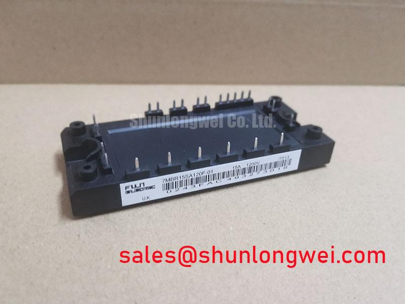
7MBR15SA120F-01 IGBT Module: Technical Data & Application Guide for 1200V/15A Compact Drives
An Engineering-Focused Overview of the Fuji Electric 7MBR15SA120F-01 S-Series Module
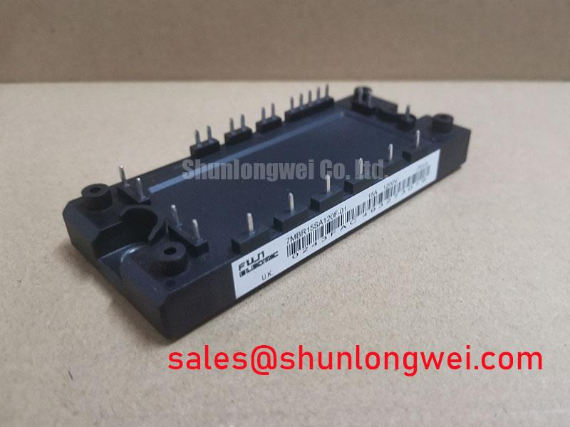
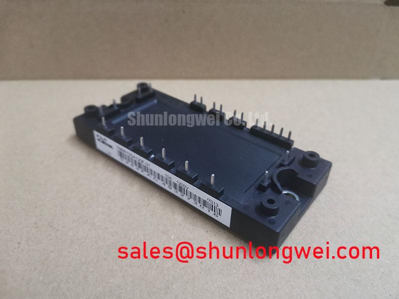
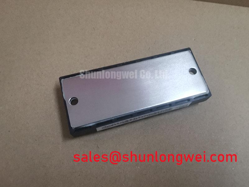
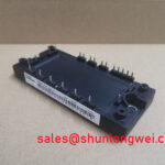
The Fuji Electric 7MBR15SA120F-01 is a highly integrated 7-in-1 power module from the S-Series, engineered to streamline the design of efficient, low-power motor drives. This Power Integrated Module (PIM) provides a complete power stage solution with specifications of 1200V | 15A | VCE(sat) 1.9V (typ). Key engineering benefits include a drastically simplified system layout and enhanced thermal performance. By combining a three-phase converter, a three-phase inverter, and a brake chopper into a single compact package, it directly addresses the critical engineering challenge of maximizing power density in space-constrained applications. For sub-4kW motor drives requiring maximum integration and efficiency, the 7MBR15SA120F-01 is the definitive choice.
Key Parameter Overview
Decoding the Specs for Integrated Drive Performance
The technical specifications of the 7MBR15SA120F-01 are optimized for efficiency and reliability in low-power motion control. The low collector-emitter saturation voltage is a critical parameter that directly minimizes conduction losses, a key factor in the module's overall high-efficiency performance. The following table highlights essential parameters with their direct engineering significance.
| Parameter | Symbol | Test Conditions | Value | Engineering Significance |
|---|---|---|---|---|
| Collector-Emitter Voltage | Vces | - | 1200V | Provides substantial voltage margin for operation on 400V to 480V AC lines, ensuring reliability against voltage spikes. |
| Continuous Collector Current (Inverter) | Ic | Tc = 80°C | 15A | Defines the module's capacity for continuous load, suitable for motors up to approximately 3.7 kW (5 HP). |
| Collector-Emitter Saturation Voltage (Inverter) | VCE(sat) | Ic = 15A, VGE = 15V, Tj = 125°C | 1.9V (Typ), 2.4V (Max) | Directly impacts efficiency by minimizing power loss during conduction. This lower "electrical friction" reduces heat generation. |
| Total Power Dissipation | Pc | Tc = 25°C, per IGBT | 85W | A key value for thermal system design, indicating the heat that must be effectively removed by the heatsink to maintain safe operating temperatures. |
| Forward Voltage (Rectifier Diode) | VF | IF = 15A, Tj = 125°C | 1.1V (Typ), 1.35V (Max) | Low forward voltage in the input rectifier stage contributes to overall system efficiency by reducing power losses during AC-to-DC conversion. |
| NTC Thermistor Resistance | R25 | Tc = 25°C | 50 kΩ ± 5% | Enables precise, real-time temperature monitoring for implementing crucial over-temperature protection logic in the drive's controller. |
Application Scenarios & Value
System-Level Benefits in Compact Motion Control Systems
The 7MBR15SA120F-01 is engineered for applications where board space, assembly simplicity, and thermal efficiency are primary design constraints. Its high level of integration makes it an optimal solution for a range of low-power industrial systems.
A high-fidelity engineering scenario is the design of a compact Variable Frequency Drive (VFD) for conveyor belt systems or commercial HVAC blowers. The challenge is to fit all power electronics into a small, often enclosed, chassis while managing the heat generated during operation. The 7MBR15SA120F-01 directly solves this by consolidating the AC-DC rectifier, DC-AC inverter, and dynamic braking chopper into a single P626 package. This single component replaces a multitude of discrete devices or multiple modules, significantly reducing the required PCB footprint and simplifying the mechanical design to a single, unified heatsink interface. The low VCE(sat) further reduces the thermal load, potentially allowing for a smaller, lower-cost heatsink or a fanless design in certain duty cycles. What is the main benefit of a 7-in-1 topology? It drastically reduces component count and simplifies system layout.
Primary applications include:
- General Purpose Inverters (up to 3.7 kW / 5 HP)
- AC Servo Drives and Spindle Drives
- Small Industrial Robots and Automation Systems
- Air Conditioning and Pump/Fan Control Units
- Uninterruptible Power Supplies (UPS)
While the 15A rating of this module is ideal for drives up to ~3.7kW, for applications requiring higher output, the related 7MBR25SA120-50 provides a 25A capability within a similar integrated framework.
Frequently Asked Questions (FAQ)
What are the primary advantages of the 7-in-1 topology in the 7MBR15SA120F-01?
The main advantages are system simplification and improved reliability. By integrating the input rectifier, output inverter, and brake chopper, it reduces component count, minimizes PCB complexity, lowers assembly costs, and decreases the number of potential failure points associated with interconnects between separate power stages.
How does the VCE(sat) of 1.9V impact the thermal design of a variable frequency drive (VFD)?
A lower VCE(sat) directly translates to lower conduction power loss (P = VCE(sat) * Ic). This means less energy is wasted as heat during operation. For a VFD designer, this allows for the use of a smaller, more cost-effective heatsink, improves overall system efficiency, and increases the thermal margin, enhancing long-term reliability. How does a low VCE(sat) improve efficiency? It minimizes conduction losses, directly reducing heat generation.
What is the function of the integrated brake chopper circuit?
The brake chopper is used for dynamic braking. When an AC motor decelerates rapidly, it acts as a generator, sending regenerative energy back to the DC bus. This can cause the DC bus voltage to rise to dangerous levels. The brake chopper circuit activates to divert this excess energy to an external braking resistor, dissipating it as heat and protecting the drive from overvoltage faults.
How should the integrated NTC thermistor be used to enhance system reliability?
The NTC thermistor provides a real-time analog of the module's internal temperature. The drive's control system should continuously monitor this feedback. It can be used to trigger tiered protection schemes: first, a warning and potential de-rating of the output current as temperature rises, followed by a complete shutdown if a critical temperature threshold is breached, preventing catastrophic failure of the IGBT module.
Is the 7MBR15SA120F-01 suitable for regenerative braking applications?
Yes, its integrated brake chopper circuit is specifically designed for these scenarios. It provides a built-in, cost-effective solution for managing the regenerative energy common in applications involving frequent starting and stopping, such as elevators, cranes, or conveyors, ensuring safe and controlled deceleration.
Technical Deep Dive
A Closer Look at the 7-in-1 Architecture for Simplified Power Stage Design
The architecture of the 7MBR15SA120F-01 represents a significant step in power module integration. To understand its value, it's helpful to deconstruct the "7-in-1" designation. This single module contains the three core functional blocks of a complete motor drive power stage: a three-phase input rectifier bridge, a three-phase output inverter, and a brake chopper. This is analogous to a modern System-on-Chip (SoC) in a smartphone, which integrates the CPU, GPU, and modem onto a single piece of silicon to save space and improve performance. This highly integrated approach in power electronics delivers similar benefits.
This integration simplifies the entire design workflow. Electrically, it eliminates the need for complex, high-current PCB traces between separate rectifier and inverter modules. Mechanically, it standardizes the thermal interface to one flat baseplate. From a procurement standpoint, it consolidates multiple line items into a single part number. For design engineers, this translates to faster development cycles, reduced manufacturing complexity, and a more compact, reliable final product, a key objective for competitive manufacturers like Fuji Electric.
From an Engineer's Perspective
For the design engineer tasked with developing a cost-sensitive and compact motor drive, the 7MBR15SA120F-01 offers a compellingly practical solution. It moves beyond simple component specifications to address system-level challenges. The value is not just in the 1200V rating or the 15A current handling, but in the reduction of design complexity. This module effectively offloads the task of integrating and thermally managing the entire power stage, allowing the engineering team to focus on control logic, software, and user interface—the areas that truly differentiate their end product in the market.