

Content last revised on October 28, 2026
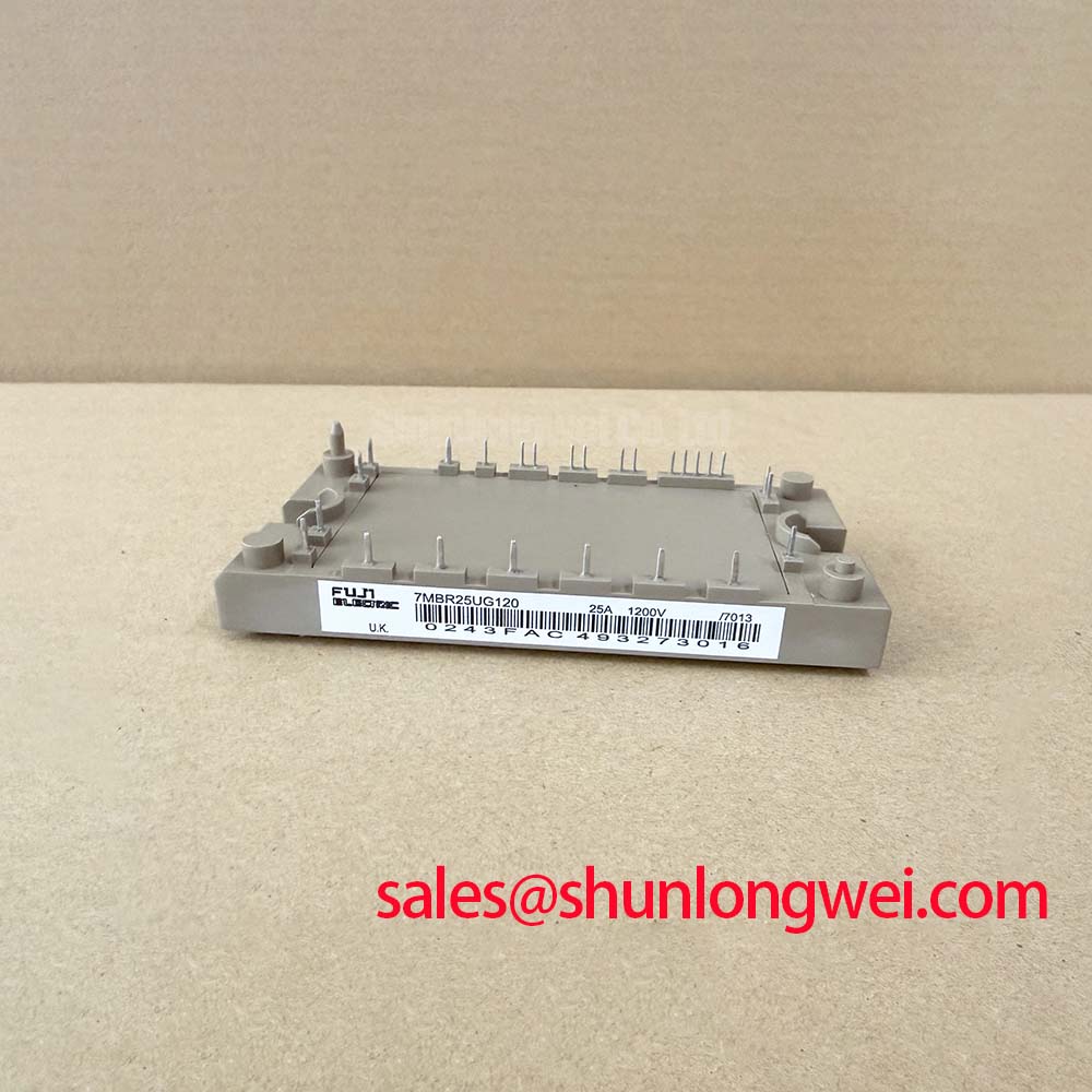
Benchtop Waveform Tuning: Mitigating Stress via Balancing Switching Dissipation vs di/dt on 7MBR25SA120-50
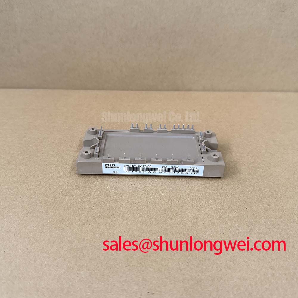
Capture the gate-emitter and collector-emitter waveforms at the module terminals before changing gate resistance on a repaired drive board. An overshoot measured through a long probe connection can send troubleshooting in the wrong direction, while a clean driver-output trace can conceal ringing at the power device. For the Fuji Electric 7MBR25SA120-50, the official specifications establish a 1200 V collector-emitter rating, a ±20 V gate-emitter limit, and collector-current ratings of 25 A DC and 50 A for a 1 ms pulse at a case temperature of 80°C.
This power integrated module requires coordinated assessment of the drive circuit, protection path, and heatsink interface. Its official specifications also include 120 W collector power dissipation per IGBT and a 150°C maximum operating junction temperature. These are device limits with distinct thermal and electrical conditions, not simultaneous operating targets. For maintenance procurement, the complete 7MBR25SA120-50 product designation should remain attached to the equipment drawing, gate-board revision, and mechanical interface record throughout the replacement assessment.
Separate turn-on behavior from turn-off behavior when evaluating the external gate-resistor network. As a Design Consideration, increasing gate resistance can slow switching and reduce some transient stress, but it can also increase switching dissipation. Reducing resistance can shorten transitions while increasing sensitivity to loop inductance and unwanted gate movement. Neither adjustment should be accepted solely because an unloaded waveform appears quieter.
Record the existing resistor arrangement and determine whether the board actually provides independent turn-on and turn-off paths. Where steering diodes separate those paths, their orientation and connection integrity influence which resistor controls each transition. Compare driver output and gate-emitter waveforms with a suitable measurement arrangement, keeping the gate-voltage reference local to the emitter connection. Change one element at a time so that a shift in overshoot, switching duration, or gate ringing remains traceable to the modification.
The official inverter characteristics give a typical VCE(sat) of 2.1 V and a maximum of 2.6 V at IC = 25 A and VGE = 15 V. That gate voltage is the stated characterization condition; it is not a universal instruction for every retrofit. A collector-emitter voltage measurement taken during a switching edge should not be compared directly with this conduction-state specification. Probe settling, current level, and the interval selected for measurement all affect the comparison.
The official switching-loss figures are 3.5 mJ typical turn-on energy and 3.1 mJ typical turn-off energy, with the supplied inverter switching conditions identifying 25 A collector current and 600 V supply voltage. These figures provide a reference for loss assessment rather than a prediction for a different gate network. As an Engineering Recommendation, assess the actual switching energy and resulting thermal behavior over the intended operating range before approving a resistor change.
Keep the gate loop distinct from the high-current commutation path wherever the board permits. Inspect repaired tracks, connector joints, and gate-return routing for changes that could introduce additional coupling. Clearance and creepage decisions belong to the equipment insulation design and applicable requirements; reducing physical spacing simply to shorten a connection is not an acceptable tuning method. When a transient changes substantially with probe position, resolve the measurement arrangement before treating it as a device characteristic.
Replacement comparisons also need to distinguish the power module from its surrounding control architecture. The 7MBP75RU2A120-50 is a separate model for engineering comparison, not an assumed interchangeable replacement. Compare terminal functions, mechanical dimensions, driver requirements, protection interfaces, and thermal conditions against the equipment documentation. For potential use in high-dynamics multi-axis CNC or robotics servo equipment, compatibility should be established at the complete drive level rather than inferred from a shared manufacturer or voltage class.
Preventing Spurious Faults: Short-Circuit Energy Let-Through Matching Guidelines for 7MBR25SA120-50
Distinguish a false protection trigger from a genuine short-circuit event by recording the protection input alongside gate voltage and collector-emitter voltage. A desaturation indication can be influenced by sensing-path behavior during switching, but it can also reflect a real failure to establish normal conduction. As a Design Consideration, examine the sensing diode path, blanking behavior, local reference movement, and driver supply during the event before altering the protection threshold or delay.
Desaturation protection and semiconductor fuses perform different jobs. The gate driver responds to an abnormal conducting state and initiates turn-off; a fuse interrupts an overcurrent path according to its time-current behavior and the circuit conditions. Soft turn-off can moderate the voltage transient produced by fault-current interruption, but an excessively extended response increases device stress. The protection timing and turn-off profile therefore belong to a coordinated system assessment, not to a generic resistor prescription.
The official 50 A, 1 ms pulse-current rating must not be interpreted as a short-circuit withstand specification. Normal pulse conduction and a high-voltage short circuit impose different stresses on the semiconductor. Short-circuit safe operating area, permitted fault duration, and protection timing require the applicable manufacturer characteristics. A pulse-current entry alone does not establish the energy the module can absorb during a DC-link fault.
For fuse coordination, compare the selected fuse’s total clearing I²t at the relevant circuit voltage and prospective fault current with the withstand information for the protected circuit elements. As an Engineering Recommendation, include DC interrupting capability, circuit time constant, capacitor discharge contribution, and the location of the fault. A fuse selected only by its continuous-current marking does not establish adequate protection. Nor does an I²t comparison by itself guarantee that a semiconductor enclosure will remain intact during every possible fault.
Trace the DC-link discharge path separately from the incoming supply path. A fault supplied locally by stored capacitor energy may develop before an upstream protective device can isolate the source. Where the schematic contains a separate rectifier or auxiliary power stage, assess that stage on its own ratings and protection requirements. The 7MBR75VB120A-70 is another module reference for topology comparison; its placement or suitability as a complementary stage cannot be inferred from its model number.
If the equipment uses parallel power paths, compare current waveforms under equivalent operating conditions rather than assuming equal sharing. A positive temperature coefficient of conduction voltage can assist static sharing in suitable devices and operating regions, but the stated VCE(sat) values for this model do not establish that behavior across its operating range. As a Design Consideration, symmetric bus connections, comparable cooling conditions, and balanced gate paths help reduce avoidable differences; actual sharing remains a measurement task.
Keep fault records specific enough to support the next repair decision. Record whether the event occurred during initial enable, acceleration, steady operation, or shutdown, together with the corresponding bus and gate traces. A protection trip that disappears after a sensing adjustment is not sufficient evidence of a completed repair: the adjusted circuit still needs to detect genuine abnormal conduction without exposing the module to an unvalidated fault interval.
7MBR25SA120-50 Circuit Protection & Reliability: Calibrating DC-Bus Low-Inductance Laminated Busbar Design
Shorten the commutation loop between the local DC-link connection and the switching path while preserving the equipment’s required insulation geometry. As a Design Consideration, closely coupled outgoing and return conductors can reduce parasitic inductance, but terminal transitions, bends, and capacitor connections often determine the remaining transient behavior. Evaluate the complete current loop rather than judging a busbar only by its broad planar section.
An Engineering Calculation can describe the first-order inductive contribution as Vpeak = VDC + Lσ × |di/dt|, where Lσ represents the relevant loop inductance and the current slope is taken for the transition under examination. This simplified relationship explains why a faster turn-off can raise collector-emitter overshoot. It does not include every effect of diode recovery, distributed capacitance, or clamping behavior. Determine the acceptable loop geometry and switching slope from measured peak voltage against the module’s 1200 V rating and the equipment’s operating conditions.
Assess a snubber at the connection where it must intercept transient current. Long snubber leads can reduce its effectiveness even when the capacitor itself appears suitable. As an Engineering Recommendation, select capacitance, voltage capability, pulse-current capability, and any damping element from the measured transient and repetitive dissipation. Check both the initial voltage peak and subsequent ringing; suppressing one feature while increasing another can leave the underlying commutation problem unresolved.
Mechanical reassembly also influences electrical repeatability. Check busbar seating, terminal alignment, insulating supports, and evidence of movement before tightening connections to the applicable assembly instructions. Do not use terminal force to pull a misaligned conductor into position. Maintain the specified clearances through the complete assembly, including fastener heads and neighboring conductive structures, rather than assessing only the nominal distance between busbar edges.
The official inverter IGBT junction-to-case thermal resistance is 1.04°C/W maximum. It describes one part of the thermal path, not the complete rise from junction to cabinet air. The module also includes an NTC thermistor specified at 50 kΩ ±5% at 25°C. That reference resistance supports a sensor-circuit check at the stated temperature; converting resistance over the operating range requires the applicable thermistor characteristic, and the reading should not be treated as an instantaneous junction-temperature measurement.
Maintenance Note: Trend terminal temperature rise and heatsink airflow during scheduled inspections, and investigate changes before increasing operating load. Set cleaning and thermal-interface inspection intervals from contamination levels, operating duty, and maintenance history rather than assigning this module an unsupported service interval. After shutdown and safe isolation, inspect accessible interface edges for displacement, check the mounting condition, and address moisture or condensation before re-energizing the assembly.
For broader selection and reliability context, the Power Electronics Masterclass provides a companion reference for system-level assessment. Fuji Electric’s power semiconductor resources provide manufacturer background on switching technologies, distinct from this module’s model-specific specifications. Close the repair record with the accepted waveform captures, protection settings, mounting inspection, and stabilized thermal observations so that the next maintenance visit can identify a real change in the assembly.