
Content last revised on June 2, 2026
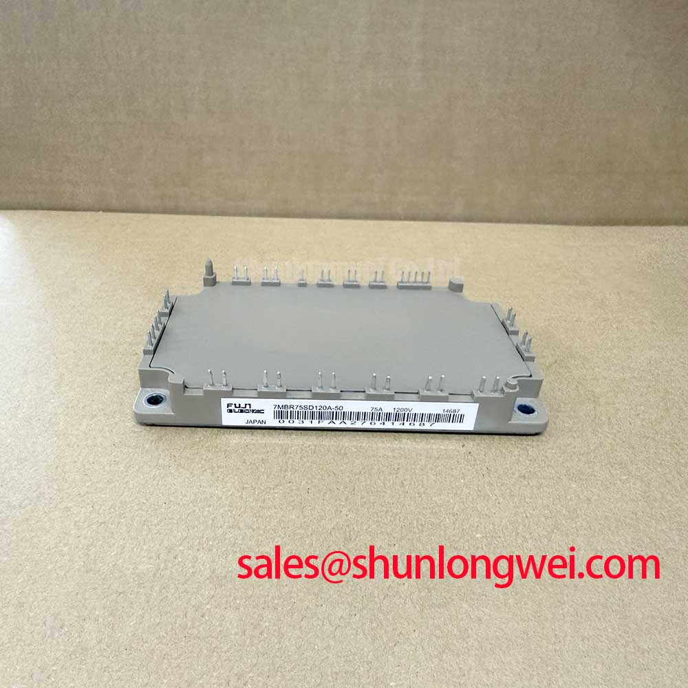
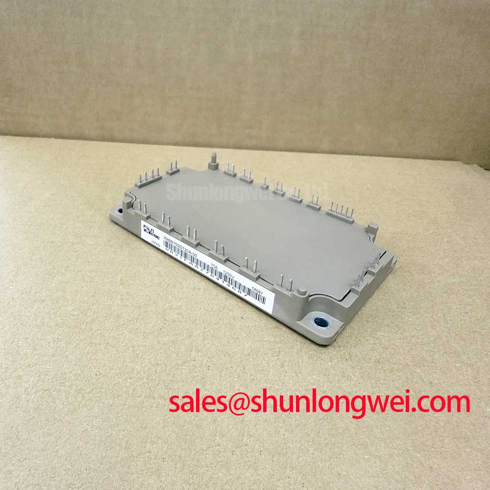
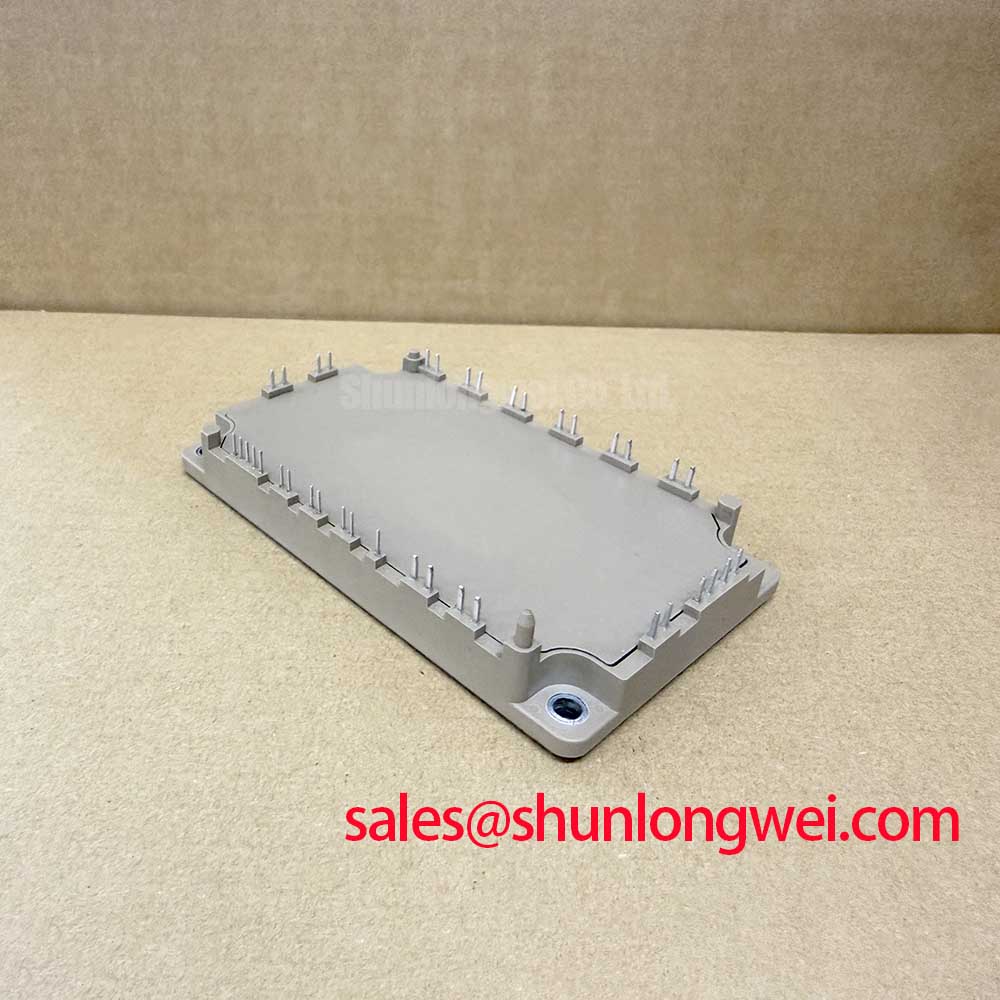
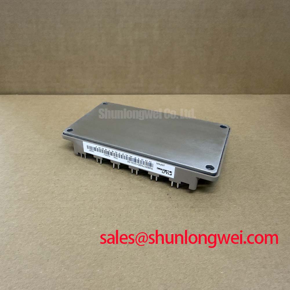
Fuji Electric 7MBR75SD120A-50: A 7-in-1 IGBT Module for High-Efficiency Power Conversion
Optimizing System Performance Through Integrated Power Stages
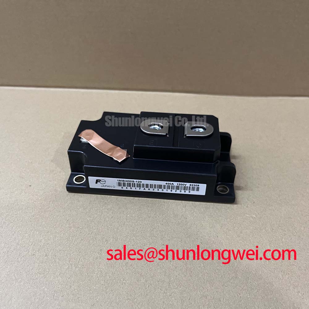
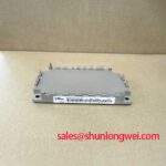
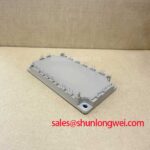
The Fuji Electric 7MBR75SD120A-50 is a highly integrated 7-in-1 power module designed to streamline the development of compact and efficient power conversion systems. Engineered for reduced conduction and switching losses, this module combines a three-phase converter, a brake chopper, and a three-phase inverter into a single package, delivering a robust solution for demanding industrial applications. Its core specifications are 1200V (Inverter) / 1200V (Brake) | 75A (Inverter) / 50A (Brake) | VCE(sat) of 2.1V (typ). The key benefits include enhanced system efficiency and simplified thermal management. This integrated design directly addresses the engineering challenge of minimizing footprint and component count in mid-power motor drives and uninterruptible power supplies. For systems requiring higher current handling in a similar integrated package, the 7MBR100VX120-50 provides an increased current rating.
Key Parameter Overview
Decoding the Specs for Efficient Power Throughput
The technical specifications of the 7MBR75SD120A-50 are tailored for balanced performance in industrial power systems. The highlighted parameters underscore its capability to manage power efficiently while maintaining thermal stability, a critical factor in achieving long-term operational reliability.
| Parameter | Inverter Section | Brake Section | Converter Section |
|---|---|---|---|
| Collector-Emitter Voltage (VCES) | 1200V | 1200V | - |
| Continuous Collector Current (IC) | 75A (TC=25°C) | 50A (TC=25°C) | - |
| Collector-Emitter Saturation Voltage (VCE(sat)) | 2.1V typ. (IC=75A) | 2.1V typ. (IC=50A) | - |
| Average Forward Current (IO) | - | - | 75A |
| Repetitive Peak Reverse Voltage (VRRM) | - | - | 1600V |
| Operating Junction Temperature (Tj) | +150°C | ||
| Isolation Voltage (Viso) | AC 2500V (1 minute) | ||
Application Scenarios & Value
System-Level Benefits in Motor Drives and Power Supplies
The 7MBR75SD120A-50 is engineered for applications where efficiency, power density, and reliability are paramount. Its 7-in-1 configuration, integrating a three-phase rectifier, brake chopper, and inverter, makes it an excellent fit for compact Variable Frequency Drive (VFD) systems up to approximately 30 kW. In a VFD, the low VCE(sat) of 2.1V directly reduces conduction losses, which is the primary source of heat when the motor is running at a steady speed. This reduction in wasted energy not only improves the overall drive efficiency but also lessens the burden on the cooling system, potentially allowing for a smaller heatsink and a more compact final product. What is the primary benefit of its integrated design? It significantly reduces assembly complexity and improves reliability by minimizing external power wiring.
This module also excels in UPS (Uninterruptible Power Supply) and AC servo drive applications. The integrated brake circuit provides a ready-made solution for managing regenerative energy from decelerating motors, protecting the DC bus from overvoltage conditions without requiring external braking units. This high level of integration simplifies the design of the power factor correction (PFC) stage and overall system layout, accelerating the development cycle for engineers.
Frequently Asked Questions (FAQ)
What does the '7-in-1' designation signify for the 7MBR75SD120A-50?
The '7-in-1' refers to the seven main semiconductor components integrated within the module: six IGBTs with six corresponding free-wheeling diodes forming a three-phase inverter, and an additional IGBT with a diode for the brake chopper circuit. It also includes the input converter stage.
How does a VCE(sat) of 2.1V at 75A impact thermal design?
A lower VCE(sat) value directly translates to lower power dissipation (P = VCE(sat) * IC) during conduction. For a system designer, this means less heat is generated for the same amount of current delivered to the load. This reduced thermal load simplifies heatsink selection, potentially reduces cooling fan requirements, and allows for higher power density within the enclosure.
What is the engineering advantage of the integrated brake chopper?
The primary advantage is design simplification and space savings. In motor drive applications, regenerative energy from a decelerating motor can cause a dangerous rise in DC link voltage. An integrated brake chopper provides a built-in mechanism to dissipate this energy as heat through a braking resistor, preventing system faults. This removes the need for designing and sourcing a separate external brake unit.
Is this module suitable for high-frequency switching applications?
The datasheet provides typical turn-on (ton) and turn-off (toff) times that support operation in the low- to mid-kilohertz range, typical for industrial motor drives and UPS systems. While not optimized for very high-frequency applications (>20kHz) where switching losses become dominant, its performance is well-balanced for its intended applications, offering a favorable trade-off between conduction and switching efficiency.
Industry Insights & Strategic Advantage
Meeting the Demands for Higher Power Density and Reliability
The trend in modern power electronics, particularly within industrial automation and motion control, is a continuous drive towards smaller, more efficient, and more reliable systems. The 7MBR75SD120A-50 directly supports this evolution. By integrating the converter, brake, and inverter stages into a single, thermally optimized package, it allows engineers to increase the power density of their designs. This is not just about making the equipment smaller; it's about reducing material costs, simplifying assembly processes, and improving overall system reliability by minimizing the number of interconnections—a common source of failure. This module's architecture is a strategic enabler for creating more competitive VFDs and servo drives that align with the efficiency mandates of modern industrial standards.
Strategic Considerations
For design engineers and procurement managers, the adoption of an integrated power module like the 7MBR75SD120A-50 represents a strategic shift from component-level to system-level optimization. The primary value lies in the reduction of design complexity, assembly time, and qualification effort. While discrete components might offer granular control over individual device selection, this integrated solution provides a pre-validated, thermally characterized power stage that significantly de-risks the project timeline. This approach allows engineering teams to focus their resources on higher-level control strategies and software development, rather than on the intricacies of power circuit layout and thermal interfacing. In a competitive market, this acceleration of the design-to-production cycle is a critical advantage.