

Content last revised on September 10, 2026
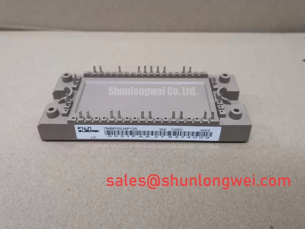
Preventing Spurious Faults: Auxiliary Emitter Return Trace Separation Guidelines for 7MBR35U4P120
For a replacement involving the 7MBR35U4P120, inspect the original control-board connection and busbar arrangement before assuming that a gate-drive fault originates in the module itself. High-current emitter return paths can share impedance with low-level gate-drive references. During rapid switching, that shared impedance can create a local voltage shift at the driver reference point, making a commanded off-state gate condition appear less secure than expected.
Design Consideration: where the equipment documentation identifies an auxiliary emitter or dedicated driver return connection, route that return separately from the main high-current emitter path as far as the physical layout permits. The purpose is to reduce mutual coupling between load current and the gate reference. The routing strategy, spacing, copper geometry, and final conductor arrangement must be validated in the complete inverter assembly because busbar geometry, capacitor placement, switching frequency, and driver layout all influence the observed waveform.
When a servo amplifier reports intermittent gate-drive, overcurrent, or desaturation-related events, examine the gate and emitter reference with an appropriately rated differential measurement method. A waveform that changes materially between low-load and high-load operation may indicate return-path coupling, connector resistance, loose mounting hardware, or a driver-side impedance issue. It does not establish a single cause on its own.
Long motor cables also deserve attention during service evaluation. Cable transmission-line reflections can raise stress at the motor end and alter inverter current behaviour, particularly during fast edge transitions. Designers should verify the original drive’s output filtering, cable specification, shielding continuity, and motor insulation requirements rather than modifying the switching network around the module without system-level tests.
For broader technical context on power-switching behaviour and module-level integration principles, refer to The Ultimate IGBT Knowledge Base. Fuji Electric also provides a manufacturer overview of power semiconductor and IPM modules.
7MBR35U4P120 Operational Boundaries: Evaluating Dynamic Gate Impedance Control for Robust Limits
The official ratings of 1200 V and 35 A define the declared voltage and current identity of the 7MBR35U4P120, but they do not replace verification of switching peak voltage, gate waveform behaviour, short-circuit protection coordination, or DC-link transient conditions in a specific drive. These operational limits are determined by the original gate driver, DC bus layout, protection circuit, cooling system, and switching conditions.
Design Consideration: high dv/dt can couple through device capacitances and cable or trace parasitics, potentially lifting the gate of a complementary switch during a transition. A driver architecture using a low-impedance off-state path, an active Miller-clamp function, or another validated gate-hold method can help resist this effect. Whether negative gate bias is used, and the value selected, must follow the original drive design and the applicable Fuji Electric device documentation. It should not be added as a universal field modification.
Desaturation monitoring is commonly used in IGBT gate-drive systems to identify an abnormal collector-emitter voltage rise while a switch is commanded on. The blanking interval, detection threshold, protection timing, and soft turn-off profile are Engineering Recommendations that must be coordinated with real switching waveforms. An incorrectly timed desaturation circuit can trip during legitimate transients, while an overly delayed response can increase fault energy.
Where a MOV or other surge-suppression network is present on the DC bus, inspect it as part of the complete protection path. Its condition, clamping behaviour, mounting location, and relationship to the local DC-link capacitor all affect transient control. Do not infer module failure from a damaged suppression component, or vice versa, without checking the surrounding bus structure and control sequence.
For equipment repair where the original approved material list identifies a related Fuji module, 7MBR35UA120 can be reviewed as a related part number. Electrical ratings, terminal assignment, package dimensions, gate-drive compatibility, thermal interface, and the equipment manufacturer’s approved substitution policy all require verification before any replacement decision.
Assembly Integrity & Layout Architecture: Implementing Thermal Time Constants and Peak Junction for 7MBR35U4P120
Before fastening the 7MBR35U4P120 to a heatsink, inspect the module base-contact area and mating surface for particulate contamination, burrs, corrosion residue, unevenness, or evidence of previous mechanical stress. The supplied official parameters confirm the device’s 1200 V and 35 A ratings, but they do not provide a confirmed mounting torque, thermal-interface thickness, junction temperature limit, thermal resistance, or transient thermal impedance value. Those values must be taken from the applicable manufacturer documentation for the exact module revision.
Design Consideration: pulsed overload evaluation requires more than average power estimation. The junction response depends on pulse duration, repetition pattern, starting temperature, heat-sink condition, and the module’s manufacturer-supplied transient thermal model. Engineers commonly use a multi-stage thermal impedance representation to estimate the temporary difference between junction and case temperature, then verify that the calculated peak remains within the approved operating boundary. The required thermal data must not be substituted with generic module assumptions.
⚠️ Field Alert: Tighten mounting hardware only to the torque specified for the exact module package and equipment assembly, because uneven clamping can degrade thermal contact or mechanically stress the case.
In a CNC or robotics servo drive, repeated acceleration and braking cycles can create varying semiconductor losses and thermal excursions. Inspect the heatsink airflow path, fan condition, thermal-interface coverage, and DC-link capacitor location before attributing overheating to the power module. In bidirectional DC bus systems, battery charge and discharge events can also change the thermal duty profile, so system engineers should verify the complete energy path during commissioning.
A related upstream rectifier or complementary power-stage item may be found in some repair bills of materials. The 7MBR15SA120 is available for neutral comparison where the equipment documentation calls for that specific part. Its role, topology, and compatibility must be confirmed from the original circuit documentation.
Benchtop Waveform Tuning: Mitigating Stress via Multi Module Parallel Current Sharing on 7MBR35U4P120
Parallel module arrangements require evidence from actual current and gate waveforms rather than an assumption that identical part numbers will automatically share dynamic current equally. At steady state, IGBT conduction behaviour can support current sharing under certain operating conditions because collector-emitter saturation characteristics vary with temperature. Dynamic sharing, however, is strongly influenced by gate-loop symmetry, driver timing, busbar inductance, individual thermal paths, and component tolerances.
Engineering Recommendation: compare each parallel path using the same measurement reference, and inspect gate-emitter voltage, collector-emitter switching behaviour, and current waveform timing during controlled tests. If one path repeatedly turns on earlier, turns off later, or carries a visibly different switching transient, investigate driver routing, connection resistance, local decoupling placement, and heatsink contact before changing gate components.
The reverse-recovery behaviour of the associated freewheel path can also influence turn-on stress and radiated noise. A harsher recovery transient may increase ringing in the commutation loop, while a softer response can change switching loss and waveform shape. The applicable module documentation and measured system waveform should govern any EMI mitigation work. Snubbers, bus capacitors, shielding, and gate impedance must be evaluated together rather than adjusted as isolated fixes.
Fuji Electric’s PIM 7 Pack product information provides manufacturer context for integrated power-module families. For the 7MBR35U4P120, retain the original controller settings where possible and validate every replacement with controlled startup checks, insulation verification, and waveform comparison against a known-good drive path.