Content last revised on January 25, 2026
6MBI15GS-060 Fuji Electric IGBT Module: Technical Analysis for Compact Motor Drives
An Engineered Solution for Efficient, Low-Power Motion Control
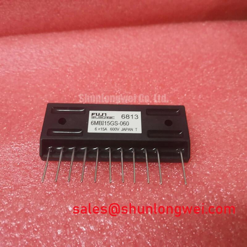
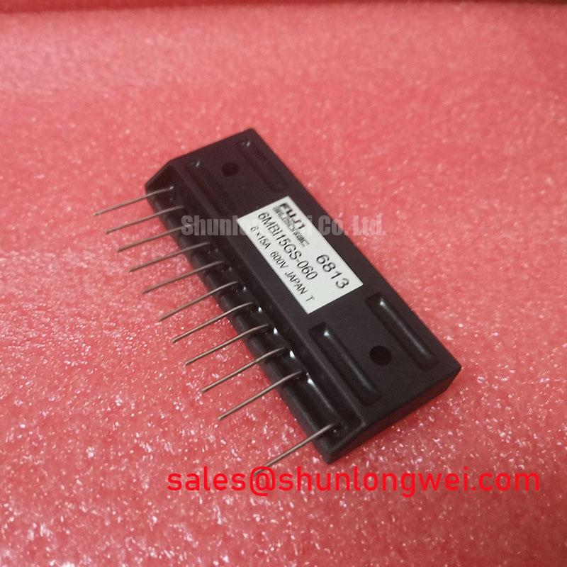
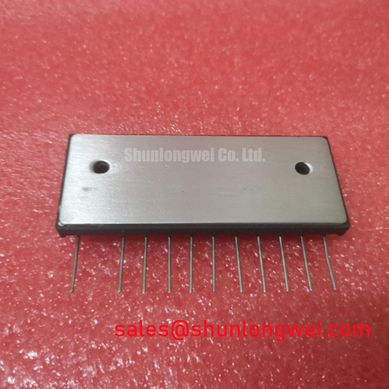
The Fuji Electric 6MBI15GS-060 is a 6-pack IGBT module engineered to deliver efficient power conversion in a compact footprint for low-power motor control. Its design focuses on minimizing losses for enhanced system reliability. What is the primary benefit of its integrated 6-pack design? It significantly simplifies the power stage layout for three-phase inverters. This module's key specifications include 600V | 15A | VCE(sat) 2.8V max. The primary engineering benefits are reduced conduction losses and a simplified thermal management design. For designers of small servo drives or general-purpose inverters, the 6MBI15GS-060 provides a robust and straightforward building block for the power conversion stage. Best fit for 200-240V AC-fed drives where thermal performance and board space are critical design constraints.
Key Parameter Overview
Decoding Key Electrical Characteristics for Motor Drive Design
The technical specifications of the 6MBI15GS-060 are tailored for reliability and performance in its target applications. The following parameters, extracted from the official datasheet, are crucial for system design and thermal modeling.
| Parameter | Symbol | Conditions | Value | Unit |
|---|---|---|---|---|
| Absolute Maximum Ratings | ||||
| Collector-Emitter Voltage | VCES | VGE=0V | 600 | V |
| Gate-Emitter Voltage | VGES | ±20 | V | |
| Continuous Collector Current | IC | 15 | A | |
| Continuous Collector Current (Pulsed) | ICP | 1ms pulse | 30 | A |
| Max. Power Dissipation | PC | One Transistor | 75 | W |
| Electrical Characteristics (IGBT Part) | ||||
| Collector-Emitter Saturation Voltage | VCE(sat) | IC=15A, VGE=15V | 2.3 (Typ) / 2.8 (Max) | V |
| Gate-Emitter Threshold Voltage | VGE(th) | IC=15mA, VCE=10V | 5.0 to 8.0 | V |
| Thermal Characteristics | ||||
| Thermal Resistance (Junction-to-Case) | Rth(j-c) | IGBT Part | 1.67 | °C/W |
| Operating Junction Temperature | Tj | +150 | °C | |
Download the 6MBI15GS-060 datasheet for detailed specifications and performance curves.
Application Scenarios & Value
System-Level Benefits in Compact Motion Control Systems
The 6MBI15GS-060 is optimized for power conversion stages in low-power industrial applications. Its primary value lies in simplifying the design of three-phase inverters, which are fundamental to modern Servo Drive and Variable Frequency Drive (VFD) systems.
Consider the engineering challenge of designing a compact servo drive for a packaging machine. Space is at a premium, and thermal management is critical to prevent overheating in a sealed enclosure. The 6MBI15GS-060 addresses this directly. Its integrated 6-pack configuration replaces six discrete IGBTs and six diodes, drastically reducing PCB footprint and simplifying assembly. More importantly, its specified VCE(sat) of 2.8V maximum directly translates to lower conduction losses. Think of VCE(sat) as a small voltage "toll" the device charges to stay on; a lower toll means less power is wasted as heat. This reduction in generated heat simplifies the heatsink requirements, enabling a smaller, more cost-effective thermal solution and contributing to higher overall system reliability.
The module is an excellent fit for motor control systems operating on 200-240V AC lines, typically powering motors up to 2.2 kW. While this model is ideal for such low-power systems, for applications requiring higher current handling or operation on 400V lines, a part like the 6MBI50S-120-02 offers a higher current rating and a 1200V breakdown voltage.
Frequently Asked Questions
Engineering Inquiries on Performance and Integration
How does the VCE(sat) of 2.8V (max) impact thermal design choices for a VFD?
A lower VCE(sat) directly reduces the power lost as heat during the conduction phase (Pd = VCE(sat) * Ic). With a maximum of 2.8V at 15A, designers can calculate a more predictable worst-case thermal load. This allows for the selection of a smaller, lighter, and often less expensive heatsink compared to a device with a higher on-state voltage, directly impacting the power density and final cost of the Variable Frequency Drive (VFD).
What is the primary advantage of a 6-pack module configuration in motion control systems?
The main advantage is integration. By housing a complete three-phase bridge in a single, thermally optimized package, it simplifies the power stage design. This reduces component count, minimizes parasitic inductance between switches (which can cause voltage overshoots), shrinks the overall PCB area, and streamlines the manufacturing process for motion control systems.
Is the 6MBI15GS-060 suitable for high-frequency Pulse Width Modulation (PWM)?
The datasheet specifies switching characteristics that support typical PWM frequencies used in motor control, generally in the range of 5 kHz to 20 kHz. Its "high-speed switching" designation for its generation indicates it was designed to balance switching losses and conduction losses effectively within this common operational range for small industrial machinery.
Application Vignette: A Technical Deep Dive
Detailed Analysis: Implementing the 6MBI15GS-060 in a Precision Servo Drive
In a high-precision CNC machine, the performance of the servo motor is paramount. The challenge for the drive designer is to maintain precise speed and torque control under varying loads, which requires a highly responsive and efficient power stage. A critical aspect is managing heat, as thermal fluctuations can affect the accuracy of control electronics and lead to premature component failure.
Using the 6MBI15GS-060 provides a clear solution path. The integrated module forms the heart of the inverter, converting the DC bus voltage into finely controlled AC waveforms via Pulse Width Modulation (PWM) signals from the controller. The module's thermal resistance, Rth(j-c), can be thought of as the quality of the "thermal highway" for heat to escape the semiconductor chip. A lower value signifies a wider, less congested highway. This allows the heat generated from both conduction and switching losses to be efficiently transferred to the heatsink.
Switching losses, which occur every time the IGBT turns on or off, are like tiny puffs of wasted energy. At a 15 kHz PWM frequency, there are 15,000 "on" and 15,000 "off" events every second for each switch. The defined switching energies (Eon, Eoff) of the 6MBI15GS-060 ensure these cumulative losses are manageable. By minimizing total thermal load (conduction + switching losses) and providing an efficient path for its removal, the module allows the servo drive to operate at a stable temperature. This thermal stability is key to ensuring the Fuji Electric IGBT module supports the long-term reliability and positional accuracy required in demanding motion control systems.
Technical Inquiries and Component Sourcing
For further technical evaluation, pricing, and availability of the 6MBI15GS-060 IGBT module, our team of specialists is available to provide detailed information and support your design process. We can assist in cross-referencing specifications and ensuring the component meets the precise requirements of your power electronics project.

