Content last revised on September 10, 2026
Preventing Spurious Faults: Dynamic Gate Impedance Control Guidelines for 7MBP75RA120-05
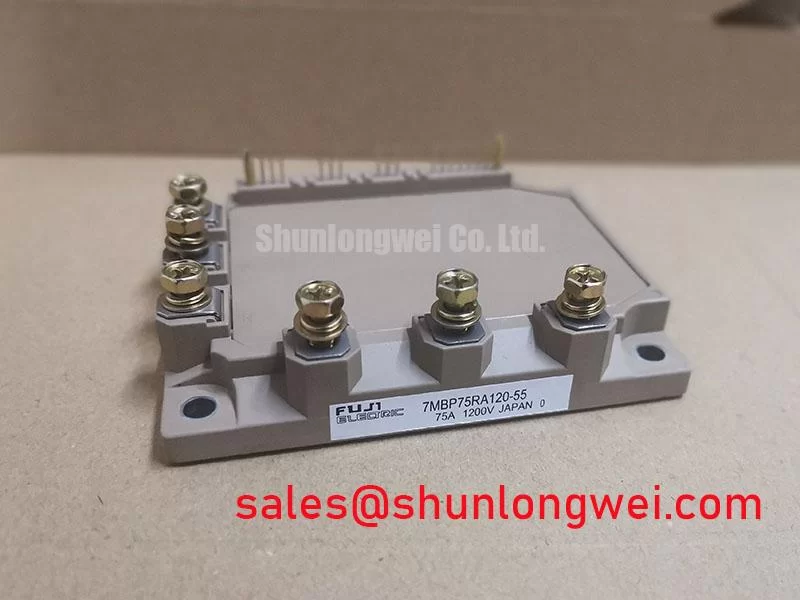
Begin a bench inspection by isolating the drive, recording the nameplate rating, and checking the module’s terminal condition before applying any control signal. The 7MBP75RA120-05 is a Fuji Electric power module with an official rated voltage of 1200 V, an official rated current of 75 A, and a Module package. These figures identify the electrical class of the replacement part, but they do not by themselves confirm compatibility with a forklift traction inverter or another power converter.
For a cold inspection, compare the resistance and diode-test behavior of the corresponding power terminals with a known-good assembly from the same equipment. The result should be treated as a comparative diagnostic indication rather than a universal pass or fail threshold. A reading that differs substantially between parallel switching paths may justify checking the gate driver, power board, DC-link discharge condition, and wiring before condemning the module.
High common-mode voltage transients can transfer through gate-driver capacitances and produce an unintended gate-voltage disturbance on the inactive switch. A Design Consideration is to control the gate-loop impedance with a short, tightly coupled driver connection and a return path that does not share the main high-current emitter route. Where the system architecture supports it, an active Miller clamp can help hold the inactive gate at a controlled potential during the opposing device’s switching interval. The choice of a negative gate bias is system-dependent and must be verified against the Fuji Electric documentation, driver insulation limits, and the actual gate-emitter rating.
Do not assume that a gate resistor value, clamp voltage, or turn-off delay from another 1200 V module can be transferred directly to this part. Designers should examine the gate waveform at the module terminals, not only at the driver output, while monitoring collector-emitter overshoot, ringing, and the timing relationship between the upper and lower switching devices. If a protection event occurs only during high-load transitions, inspect the driver supply stability, desaturation protection timing, current-sense path, and commutation loop together.
Desaturation protection and soft turn-off require coordinated system testing. The module rating confirms the voltage and current class, while the actual short-circuit withstand behavior, gate charge, VCE(sat), switching energy, and safe operating limits must come from the applicable Fuji Electric data for the exact revision. A field engineer should verify whether a fault waveform is a genuine overcurrent event or a false trigger caused by layout coupling, inadequate blanking control, or a disturbed sense reference.
For an electric material-handling vehicle, the inverter may operate through repeated acceleration, braking, and low-speed torque transitions. This makes gate-loop symmetry important even when the average motor current appears moderate. The system integrator should confirm the required switching frequency, protection sequence, and thermal operating point from the original drive design rather than deriving them from the 75 A label alone. Fuji Electric’s Power Semiconductor and IPM Modules information provides useful manufacturer-level context for evaluating module families and application constraints.
Preventing Spurious Faults: Thermal Paste Degradation Prevention and Maintenance Guidelines for 7MBP75RA120-05
After electrical screening, inspect the mounting surface for burrs, contamination, uneven contact, and evidence of previous thermal-interface failure. The 7MBP75RA120-05 is specified here only as a module with a 1200 V rating and a 75 A rating; a detailed baseplate flatness limit, thermal resistance value, allowable junction temperature, or mounting torque should be taken from the exact Fuji Electric mechanical and thermal documentation.
A uniform thermal interface layer is a Design Consideration, not an official parameter established by the basic product data above. Excess compound can increase thermal resistance, while insufficient coverage can leave air gaps beneath the baseplate. The practical objective is continuous contact with controlled compound spread, without relying on thick material to compensate for a warped heatsink. If the existing thermal interface has hardened, separated, or migrated, remove it using a process compatible with the module base and heatsink finish before installing the replacement.
Fasteners should be tightened progressively and in a sequence that distributes pressure across the mounting area. The correct torque is determined by the fastener size, washer arrangement, heatsink material, and Fuji Electric installation instructions. It should not be copied from a different module family. ⚠️ Field Alert: Disconnect the DC link and verify the measured discharge condition before touching the module terminals or removing its gate-drive connector.
Thermal inspection should continue after the inverter reaches its normal operating state. Compare temperatures across phases and check whether one switching position runs hotter under a repeatable load. An uneven result can involve interface contact, current sharing, gate timing, motor-cable conditions, or a phase-leg measurement error. Infrared readings should account for surface emissivity and the location of the measurement point; they are useful for comparison but do not directly provide junction temperature.
In traction service, phase-angle conduction, regenerative braking, and line-frequency ripple from the energy-storage system can create different thermal patterns. A bidirectional DC-DC battery interface may also produce alternating heating during charge and discharge. The correct response is to assess the complete thermal cycle, including heatsink airflow, enclosure temperature, switching loss, conduction loss, and the control strategy. Specific lifetime extension claims require field or laboratory evidence for the complete assembly and should not be assigned to the module without a documented source.
RC snubbers, clamp networks, and ripple-smoothing components can reduce transient stress when correctly tuned, but their values are determined by the converter topology and measured waveform. Engineers should verify capacitor voltage stress, resistor pulse capability, parasitic inductance, and dissipation during switching tests. Fuji Electric’s PIM 7-Pack reference can help distinguish product-family information from the application-specific limits that must be checked in the relevant datasheet.
Benchtop Waveform Tuning: Mitigating Stress via Transmission-Line Impedance Mismatch: Sizing Guidelines for 7MBP75RA120-05
When a replacement module is installed in a forklift drive, capture the phase-node waveform at the inverter output and compare it with the original known-good signal path. Long motor leads, cable shielding, termination behavior, and motor impedance can interact as a transmission system. Reflections may increase the voltage seen at the motor terminals and can also feed disturbances back toward the inverter, but the actual peak depends on cable construction, installation geometry, switching edge rate, DC-link voltage, and measurement technique.
A voltage probe with a long ground lead can create ringing that is not present in the equipment. Use a properly rated differential probe with the shortest practical connection arrangement, confirm probe compensation, and compare the result at multiple locations. The engineer should verify the peak margin against the module’s documented voltage rating and the converter’s DC-link operating range during controlled switching tests. The 1200 V rating of the 7MBP75RA120-05 is an official product parameter, not permission to operate the complete system at that value.
Output chokes, dv/dt filters, and sinusoidal filters may be evaluated when motor-cable reflections or conducted noise exceed the system target. Their selection is a system calculation based on motor insulation requirements, carrier frequency, current ripple, filter heating, resonance, and control-loop interaction. Avoid inserting a filter without checking whether the inverter control software, current feedback, and braking response remain stable.
For a low-voltage traction system, repeated direction changes and regenerative events can expose transient problems that do not appear during a steady unloaded spin. Test forward drive, reverse drive, acceleration, deceleration, and fault recovery under controlled conditions. If an overvoltage alarm appears during only one operating transition, inspect the braking chopper, DC-link measurement, cable routing, and probe reference before attributing the event to the power module.
The 7MBR35UA120 may be included in a neutral compatibility review where the equipment documentation identifies it as an applicable alternative family, but voltage, current, pin arrangement, protection behavior, mechanical dimensions, and thermal requirements must be confirmed before any substitution. For a broader power-stage assessment, the 6MBI450U-120A-05 can be evaluated as a related front-end or auxiliary-stage component when the original topology calls for that function.
Benchtop Waveform Tuning: Mitigating Stress via PCB Gate Loop Layout Symmetry on 7MBP75RA120-05
Inspect the gate-drive board for unequal trace lengths, narrow return paths, cracked solder joints, connector fretting, and routing that places control conductors beside high-current commutation paths. The gate loop should be treated as a high-speed switching circuit. Its power return and signal reference must be arranged to limit shared inductance and prevent the main emitter current from modulating the driver reference.
Do not assume a Kelvin emitter connection or auxiliary emitter terminal unless it is explicitly identified in the exact Fuji Electric terminal diagram for this model. Where the manufacturer’s layout documentation provides separate control and power returns, keep those functions distinct and route them as a matched pair. Where such a terminal arrangement is not confirmed, the system integrator should verify the connector and terminal assignment from the original module documentation before modifying the PCB.
On the bench, compare the gate-emitter waveform at each switching position during turn-on and turn-off. Look for unequal amplitude, delayed transitions, overshoot, and persistent oscillation. A difference between phases may indicate driver mismatch, connector resistance, parasitic coupling, or a damaged gate path. Confirm the finding with continuity checks while unpowered and with oscilloscope measurements under safe, current-limited test conditions.
Desaturation fault handling should be checked as a complete sequence: fault detection, gate pull-down, soft turn-off, controller isolation, and reset authorization. The required timing is determined by the device’s short-circuit behavior and the system’s available protection hardware. Engineers should obtain the applicable Fuji Electric switching and protection data rather than assigning a generic SCSOA, ITSM, or recovery window to this model.
For long-duration evaluation, record phase current, DC-link voltage, heatsink temperature, gate waveform, and fault history together. This supports separation of electrical overstress from thermal-interface problems and battery-side cycling effects. The related Industrial Applications resource offers application context, while model-specific limits remain subject to the manufacturer’s documentation and the completed system validation.