


Content last revised on February 5, 2026
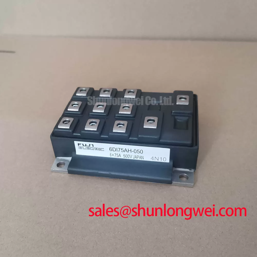
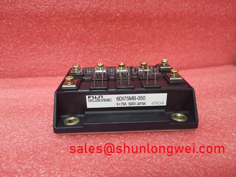
6DI75MB-050 | Fuji Electric 75A 500V 6-in-1 IGBT Module
An In-Depth Engineering Review
Engineered for thermal resilience in compact three-phase inverters, the Fuji Electric 6DI75MB-050 Power Transistor Module ensures operational stability in demanding industrial applications. This device integrates six IGBTs into a single, efficient package, defined by key specifications of 500V | 75A | 800W Pc. The primary engineering benefits include substantial thermal headroom for robust designs and a simplified inverter topology that accelerates development. With its 500V rating, the module provides a reliable safety margin for power stages operating on 200-240V AC lines. For cost-sensitive 240V motor drives up to approximately 15 kW that demand a straightforward and reliable power stage, the 6DI75MB-050 presents an optimally integrated solution.
Application Scenarios & Value
System-Level Advantages in Motor Drives and Power Conversion
The 6DI75MB-050 is engineered for core applications where efficient power conversion and reliable motor control are critical. Its architecture is particularly well-suited for the construction of a Variable Frequency Drive (VFD) and other three-phase inverter systems operating on 200V-class mains. In these applications, designers are often challenged with managing heat within progressively smaller enclosures to increase power density and reduce system cost.
Consider the design of a compact motor drive for an industrial conveyor system. The drive must handle frequent start-stop cycles and varying loads, which generate significant thermal stress. The 6DI75MB-050's substantial 800W power dissipation capability directly addresses this challenge. This high thermal budget provides engineers with the necessary headroom to maintain a safe junction temperature, ensuring long-term reliability without requiring an oversized or complex cooling apparatus. This simplifies the overall Heatsink Design and allows for a more compact and cost-effective final product. While the 6DI75MB-050 is optimized for 200-240V systems, applications requiring operation on 400/480V AC lines may benefit from a higher voltage device like the CM200DY-24H, which provides a 1200V blocking voltage.
Key Parameter Overview
Decoding Key Specifications for Thermal Management and Reliability
The performance of the 6DI75MB-050 is defined by its electrical and thermal characteristics. The following table highlights the critical parameters that directly inform system design and component selection. The collector power dissipation is a pivotal metric, setting the upper boundary for the module's thermal handling capacity.
| Parameter | Symbol | Value | Unit |
| Collector-Emitter Voltage | Vces | 500 | V |
| Gate-Emitter Voltage | VGES | ±20 | V |
| Continuous Collector Current | Ic | 75 | A |
| Peak Collector Current | Icp | 150 | A |
| Collector Power Dissipation (Tc=25°C) | Pc | 800 | W |
| Operating Junction Temperature | Tj | +150 | °C |
| Storage Temperature | Tstg | -40 to +125 | °C |
Technical Deep Dive
A Closer Look at Thermal Design Implications of the 800W Power Dissipation
The 800W power dissipation (Pc) rating is the cornerstone of the 6DI75MB-050's thermal design philosophy. This value is not merely a theoretical limit; it is a practical engineering parameter that dictates the total amount of heat—generated from both conduction and switching losses—that the module can safely transfer to its heatsink while the case temperature is held at 25°C. In real-world scenarios, this figure is the starting point for calculating the required performance of the cooling system to keep the IGBT junction temperature below its 150°C maximum.
Think of the 800W rating as the module's 'heat budget.' A larger budget provides engineers more flexibility to push the device in higher frequency or higher current conditions while staying within safe thermal limits. The thermal path from the IGBT chip to the ambient environment can be visualized as a series of resistances. The module's internal construction is optimized to minimize its own thermal resistance (Rth(j-c)), but its high Pc rating places greater emphasis on the external thermal path: the thermal interface material (TIM) and the heatsink itself. Proper selection and implementation of these external components are essential to fully leverage the module's power handling capability and ensure the system's long-term operational reliability.
Frequently Asked Questions
Engineering Inquiries on Performance and Integration
What is the primary application for a 500V Vces rating on the 6DI75MB-050?
A 500V Vces rating is specifically targeted for power conversion systems connected to 200V to 240V AC lines. This provides an essential safety margin to withstand voltage transients and spikes common in industrial environments, without the potential performance trade-offs of using a higher-voltage (e.g., 1200V) device in a lower-voltage application.
How does the 800W collector power dissipation (Pc) influence heatsink selection?
The 800W Pc rating is a direct input for thermal calculations. Engineers use this value along with the module's thermal resistance and calculated power losses to determine the required thermal performance of the heatsink. A higher Pc value means the module can transfer more heat, potentially allowing for a smaller, lower-cost heatsink compared to a module with a lower dissipation rating under the same operating conditions.
What are the main advantages of using a 6-in-1 integrated module versus six discrete IGBTs for a three-phase inverter?
The primary advantages are design simplification and improved reliability. An integrated module like the 6DI75MB-050 significantly reduces component count, simplifies PCB layout, and minimizes assembly complexity. Electrically, it reduces stray inductance between switches, which can lead to lower voltage overshoots and cleaner switching. For more insights on this trade-off, see this guide on IPM vs. Discrete IGBTs.
Is the 75A continuous current rating specified at the maximum junction temperature?
Typically, a datasheet's headline current rating is specified at a fixed case temperature (e.g., Tc = 25°C or 80°C), not the maximum junction temperature. As the operating temperature increases, the achievable continuous current must be derated. It is critical for engineers to consult the Safe Operating Area (SOA) curves in the official datasheet from a manufacturer like Fuji Electric to determine the permissible current at their specific operating temperature.
By offering a robust thermal platform in a compact, integrated package, the 6DI75MB-050 provides a strategic component for developing efficient and reliable power electronics. Its balanced specifications support the broader industry goal of creating higher-density power solutions without compromising on long-term performance.