

Content last revised on February 5, 2026
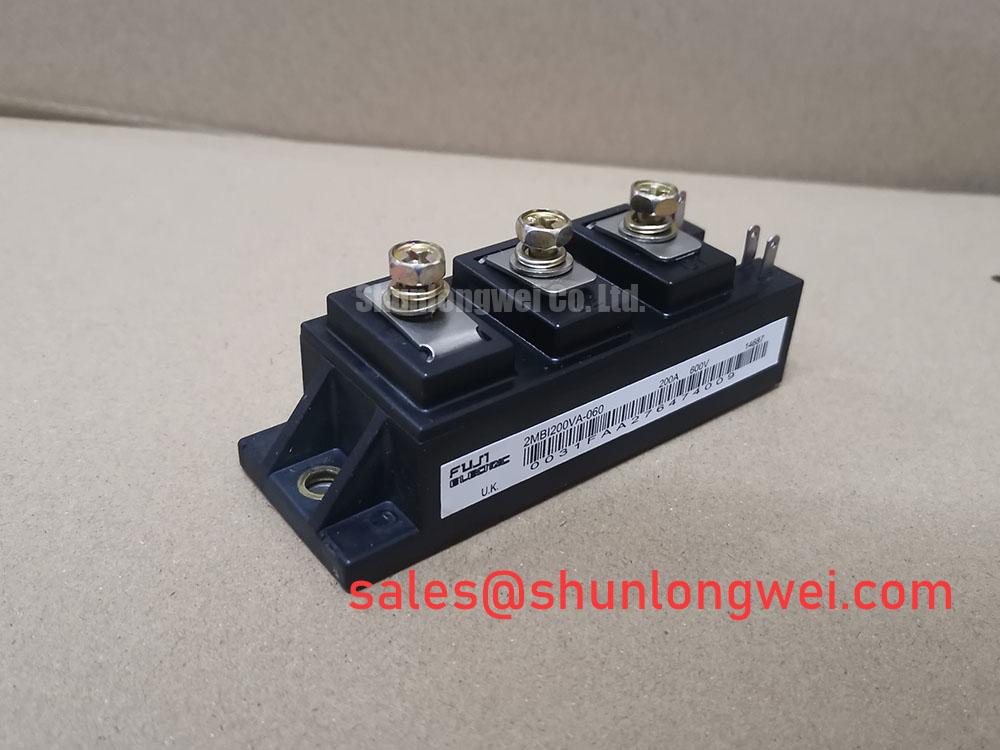
Fuji Electric 2MBI200VA-060-50: A Technical Review of the 600V/200A V-Series IGBT Module
High-Efficiency Power Conversion
Driving Performance in Motor Drives and UPS
The Fuji Electric 2MBI200VA-060-50 is a 6th generation V-series IGBT module engineered to deliver a superior balance of low power loss and robust performance in high-frequency switching applications. This 2-in-1, half-bridge module integrates two IGBTs with anti-parallel diodes, offering key specifications of 600V | 200A | VCE(sat) 1.8V (typ). The design prioritizes high operational efficiency and excellent thermal performance. By leveraging advanced chip technology, this module effectively reduces both conduction and switching losses, directly addressing the core challenge of minimizing waste heat in compact power systems. For industrial drives and power supplies where thermal management dictates system density and reliability, the 2MBI200VA-060-50 provides a decisive advantage. With its low VCE(sat) and optimized switching characteristics, this module is the best fit for medium-power inverter designs up to 20 kHz that demand high efficiency and thermal stability.
Key Parameter Overview
Decoding the Specs for Enhanced Switching Performance
The technical specifications of the 2MBI200VA-060-50 are foundational to its performance in demanding power electronics. The data below, sourced from the official datasheet, highlights the key electrical and thermal characteristics that enable engineers to optimize their designs for efficiency and reliability.
| Characteristic | Symbol | Value | Conditions |
|---|---|---|---|
| Absolute Maximum Ratings (at Tc=25°C) | |||
| Collector-Emitter Voltage | VCES | 600V | - |
| Continuous Collector Current | IC | 200A | TC=125°C |
| Max Junction Temperature | Tvj max | 175°C | - |
| Electrical Characteristics (at Tj=125°C) | |||
| Collector-Emitter Saturation Voltage | VCE(sat) | 2.10V (typ) | IC=200A, VGE=15V |
| Gate-Emitter Threshold Voltage | VGE(th) | 6.7V (typ) | IC=200mA, VCE=20V |
| FWD Forward Voltage | VF | 1.60V (typ) | IF=200A, VGE=0V |
| Thermal Characteristics | |||
| Thermal Resistance (IGBT) | Rth(j-c) | 0.23 °C/W (max) | Per device |
| Thermal Resistance (FWD) | Rth(j-c) | 0.41 °C/W (max) | Per device |
Download the 2MBI200VA-060-50 datasheet for detailed specifications and performance curves.
Application Scenarios & Value
Achieving System-Level Benefits in High-Frequency Power Conversion
The 2MBI200VA-060-50 is engineered for mid-power applications where efficiency is a critical design parameter. Its primary value is demonstrated in systems like industrial Variable Frequency Drives (VFDs), Uninterruptible Power Supplies (UPS), and commercial welding power supplies. In a VFD, for example, the inverter stage is responsible for synthesizing the AC waveform to control motor speed. The low VCE(sat) of 1.8V (typically at 25°C) directly translates to lower conduction losses during operation. This reduction in wasted energy is significant; it's the difference between needing a larger, more expensive heatsink and designing a more compact, cost-effective system. This focus on efficiency makes it a strong candidate for developers aiming to meet stringent energy standards while improving overall system reliability through better thermal management. While the 2MBI200VA-060 is optimized for 600V-class systems, for applications requiring operation on higher voltage lines, the related 2MBI200NB-120 offers a 1200V rating at a similar current capacity.
Technical Deep Dive
A Closer Look at the V-Series Technology for Loss Reduction
The core of the 2MBI200VA-060-50's performance lies in its use of Fuji Electric's 6th generation V-series IGBT technology. This technology employs an advanced trench-gate and field-stop (FS) chip structure to achieve a superior trade-off between collector-emitter saturation voltage (VCE(sat)) and switching losses (Eon/Eoff). The low VCE(sat) is a critical parameter because it dictates the power dissipated as heat while the IGBT is in its 'on' state. Reducing this value is analogous to improving the fuel economy of a car; for a given power output, less energy is wasted. This efficiency is particularly impactful in applications with high duty cycles, such as motor drives operating at constant speeds or the inverter stage of a solar or UPS system. The optimized carrier profile of the FS structure also contributes to faster, more controlled turn-off characteristics, which minimizes switching losses and enables effective operation at higher frequencies.
Frequently Asked Questions (FAQ)
How does the low VCE(sat) of the 2MBI200VA-060-50 impact system design?
The low typical VCE(sat) of 1.8V (at 25°C) and 2.1V (at 125°C) directly reduces conduction power losses (P = VCE(sat) * Ic), a major source of waste heat in power converters. This allows engineers to either reduce the size and cost of the required heatsink, increase the system's power density, or improve reliability by operating at a lower junction temperature.
What is the primary benefit of this module's dual IGBT configuration?
The 2-in-1 or half-bridge configuration simplifies the design of common inverter and converter topologies. It provides a building block for three-phase inverters (using three modules) or single-phase full-bridge circuits (using two modules), reducing component count and simplifying PCB layout compared to using discrete IGBTs.
For engineering teams designing high-efficiency power conversion systems, the 2MBI200VA-060-50 offers a compelling combination of low losses and proven V-series reliability. Exploring a deep dive into IGBT datasheets can further empower your component selection process for your next project.

