

Content last revised on September 10, 2026
Mitigating Hard Switching Transients via Active Desaturation Soft Shutdown
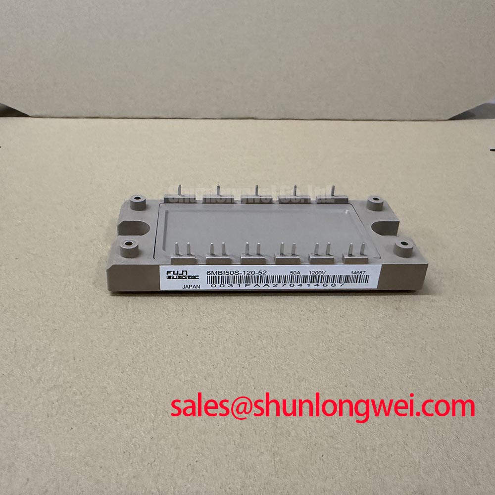
In heavy-duty variable frequency AC motor drives, short-circuit faults present severe thermal and electrical stresses to inverter power stages. The 6MBI50S-120-52 by Fuji Electric is rated at VCES = 1200V (Official Datasheet Specification) with a continuous collector current rating of IC = 50A at TC = 80°C (Official Datasheet Specification) and a peak pulse current of ICP = 100A (Official Datasheet Specification). When a phase-to-phase or phase-to-ground fault occurs, the module must withstand short-circuit conditions within the short-circuit safe operating area (SCSOA) duration of less than 10 µs. A standard hard turn-off under fault currents exceeding three times the nominal collector current triggers extreme voltage spikes due to stray loop inductance, risking immediate avalanche breakdown.
Implementing active desaturation (DESAT) detection requires setting the blanking capacitor to clear the transient state during IGBT turn-on while reacting fast enough before thermal runaway occurs. Once desaturation is detected across the collector-emitter path, the gate driver must initiate a two-stage soft turn-off. By stepping down the gate voltage gradually rather than discharging it instantaneously, the rate of current decay di/dt is controlled. This prevents inductive overvoltage from exceeding the 1200V ceiling without relying solely on large snubber circuits. In topologies incorporating auxiliary or multi-level braking networks, designers often evaluate specialized dynamic braking units such as Fuji Electric Brake Chopper IGBT Modules or balance auxiliary supplies using lower-capacity units like the 6MBI25F-120.
Calculating Failures-in-Time (FIT) Rates in High-Altitude Solar and Wind Farms
Deploying power modules in renewable applications or high-altitude industrial drives (>2000 meters) elevates cosmic ray terrestrial neutron interaction. Atmospheric neutrons collide with the silicon lattice, potentially triggering Single Event Burnout (SEB). Because catastrophic SEB happens spontaneously without prior thermal warning, derating the DC-bus voltage headroom is the primary engineering safeguard.
For the 6MBI50S-120-52, running at an operational junction temperature range of Tj = -40 to +150°C (Official Datasheet Specification) and a per-IGBT maximum power dissipation of PC = 250W (Official Datasheet Specification), steady-state DC-bus voltage selection determines operational reliability. Applying an empirical derating model (Design Consideration based on terrestrial neutron radiation standards), reducing the working bus voltage from 850V down to 700V reduces the calculated FIT rate by more than two orders of magnitude at 2500m elevation. Proper dead-time insertion also protects against shoot-through during rapid line shifts; an initial setting of tdead = 2.5 µs (Typical Starting Point for bench tuning) provides a baseline margin against switching jitter. Quantitative evaluation protocols and thermal cycler validation procedures are detailed in the Field Engineer’s Handbook.
Transmission Line Impedance Mismatch: Sizing dv/dt Output Filters and Chokes
In industrial drives operating with motor cables exceeding 30 to 50 meters, the surge impedance mismatch between the shielded transmission cable and the motor stator winding causes voltage reflection. The output switches with a maximum saturation voltage of VCE(sat) = 2.8V at Tj = 125°C and IC = 50A (Official Datasheet Specification). Steep switching edges generate dv/dt rates frequently exceeding 8 kV/µs, producing peak reflections up to twice the nominal DC-bus voltage at motor terminals.
To preserve stator insulation life and mitigate motor bearing discharge currents, output chokes or LC low-pass filters are deployed. An iron-powder or nanocrystalline common-mode choke should be sized to suppress peak phase-to-phase edge rates below 5 kV/µs (General Industry Design Consideration). When managing retrofit projects where physical footprints or thermal dissipation profiles vary, hardware teams often reference alternative series configurations such as the 6MBI50J-120, or inspect modern reverse-conducting architectures outlined in Fuji Electric RC-IGBT Modules to evaluate freewheeling diode characteristics and recovery losses.
Auxiliary Emitter Return Trace Separation for Rapid dv/dt Transients
The gate-emitter threshold of the 6MBI50S-120-52 spans VGE(th) = 5.0 to 8.0V (Official Datasheet Specification). Maintaining steady gate control during severe transient switching requires rigorous PCB layout rules. If the gate drive return path shares trace area with the high-current power emitter path, inductive voltage drop across the parasitic emitter inductance injects negative feedback into the gate loop during turn-on, increasing switching losses, or induces false parasitic turn-on via Miller capacitance during rapid turn-off dv/dt.
💡 Pro Tip: Always run the auxiliary Kelvin emitter connection directly from the module pin to the driver ground pin as an isolated, tightly coupled differential pair with the gate trace. Avoid tying auxiliary signal ground to the main power return bus on the inverter power card; keep the loop area under 2 cm² to minimize stray inductance.
The junction-to-case thermal resistance is rated at Rth(j-c) = 0.50°C/W per IGBT (Official Datasheet Specification). Consistent thermal transfer relies on applying a uniform layer of thermal interface material at 100 µm thickness and torquing mounting screws in a two-stage sequence to prevent localized mechanical stress across the ceramic DBC substrate.