


Content last revised on June 2, 2026
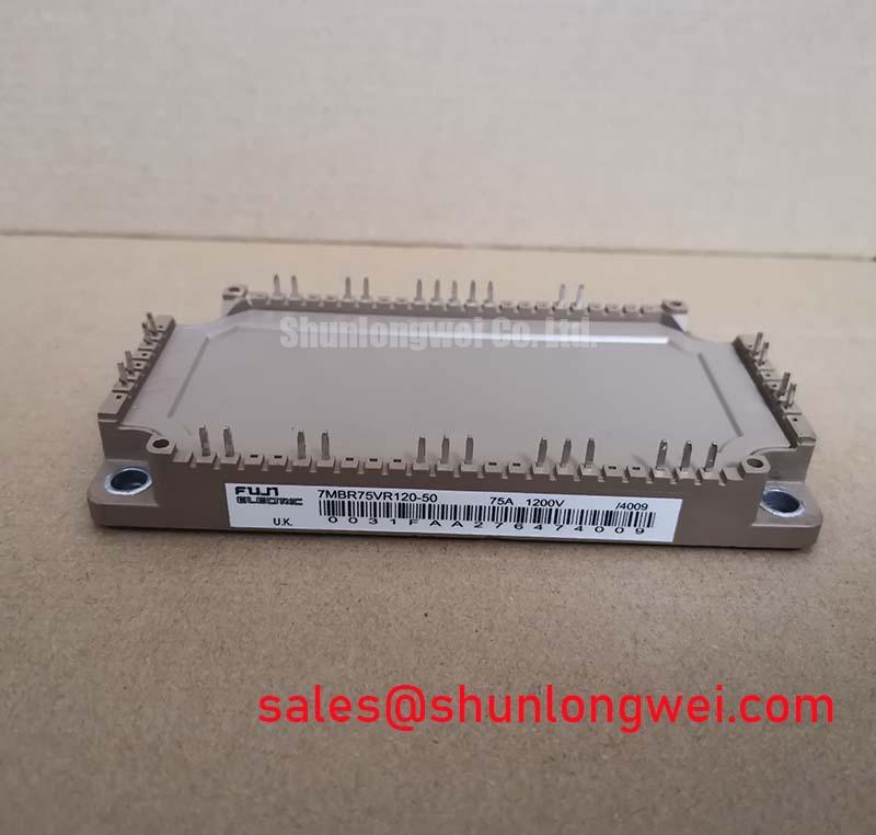
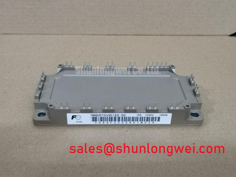
7MBR75VB120-50 IGBT Module: An Engineer's Guide to Low-Loss 75A, 1200V Power Conversion
An Integrated Power Solution for High-Efficiency Inverters
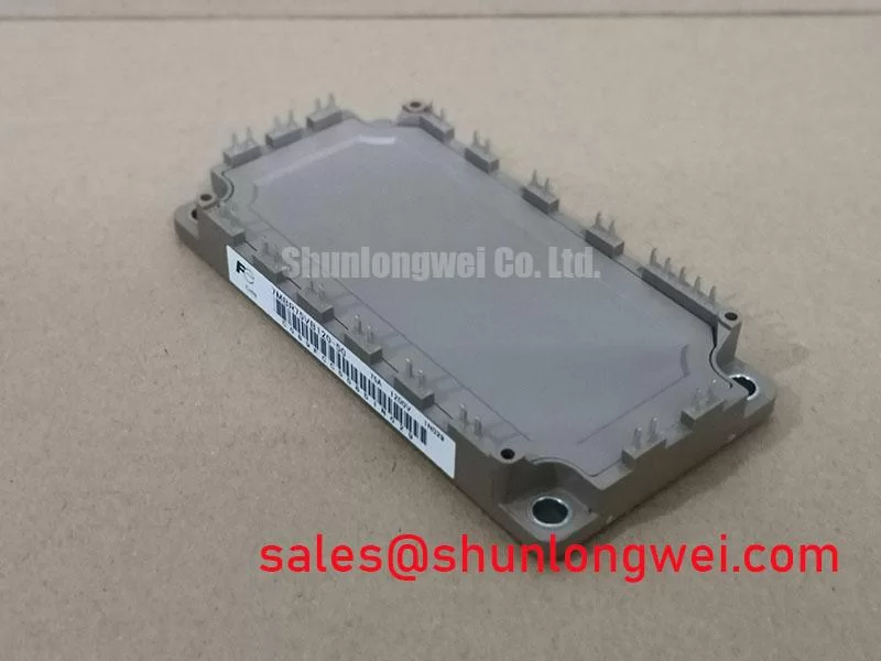
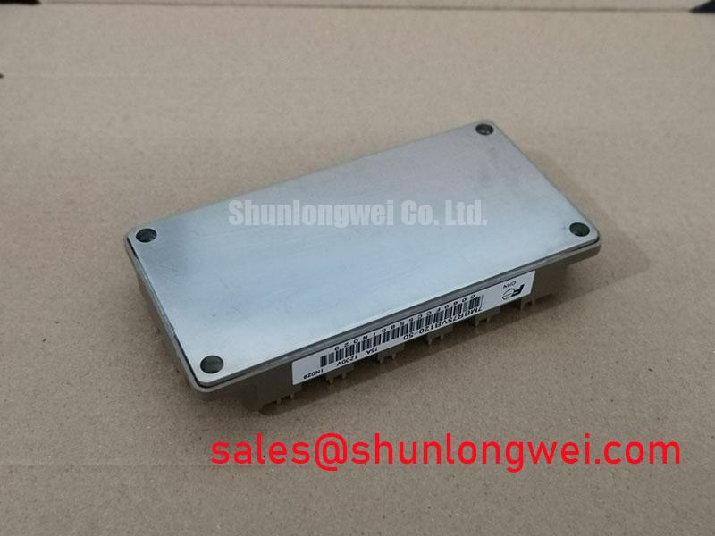
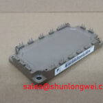
The Fuji Electric 7MBR75VB120-50 is a highly integrated 7-in-1 IGBT module engineered to maximize inverter efficiency and simplify thermal design through its exceptionally low VCE(sat). This power module combines a robust 1200V breakdown voltage with a 75A continuous collector current rating and a typical VCE(sat) of just 1.70V. Its key benefits include significantly reduced conduction losses and simplified system assembly, directly addressing the core challenges in modern power conversion design. This module's 7-in-1 configuration within a compact P626 package is specifically designed to reduce the footprint and complexity of low-to-medium power motor drive systems.
Application Scenarios & Value
System-Level Benefits in Industrial Motion Control and General-Purpose Inverters
For designers of AC drives up to 30 kW prioritizing efficiency and compact design, the 7MBR75VB120-50 offers an optimal balance of integration and low-conduction-loss performance. The primary application space for the 7MBR75VB120-50 is in power conversion systems where high efficiency and thermal stability are critical. This includes general-purpose inverters, small to medium-sized Variable Frequency Drives (VFDs), and servo drives for industrial automation and robotics.
Consider an engineering challenge in developing a compact VFD for a conveyor system. The thermal budget is tight, and a large, costly heatsink is undesirable. The low VCE(sat) of this module becomes a decisive advantage. By minimizing conduction losses—the primary source of heat in many motor control applications—the 7MBR75VB120-50 generates less waste heat. This allows engineers to specify a smaller, more cost-effective heatsink, directly contributing to a reduction in the final product's size, weight, and bill of materials (BOM). The integrated configuration also simplifies the power stage layout, leading to faster development cycles. While the 75A rating serves a wide range of applications, systems with lower power requirements may benefit from the related 7MBR50VP120-50.
Key Parameter Overview
Core Electrical and Thermal Specifications for System Design
The following parameters for the 7MBR75VB120-50 are critical for system design, simulation, and thermal modeling. The values are derived from the official manufacturer's datasheet and represent performance under specified test conditions.
| Parameter | Symbol | Value | Conditions |
|---|---|---|---|
| Absolute Maximum Ratings | |||
| Collector-Emitter Voltage | Vces | 1200V | |
| Gate-Emitter Voltage | Vges | ±20V | |
| Collector Current (Continuous) | Ic | 75A | Tc=25°C |
| Collector Power Dissipation (per IGBT) | Pc | 340W | |
| Inverter Section Electrical Characteristics | |||
| Collector-Emitter Saturation Voltage | VCE(sat) | 1.70V (typ), 2.20V (max) | Ic=75A, Vge=15V, Tj=25°C |
| Turn-on Switching Loss | Eon | 7.0 mJ (typ) | Ic=75A, Vcc=600V, Tj=125°C |
| Turn-off Switching Loss | Eoff | 7.5 mJ (typ) | Ic=75A, Vcc=600V, Tj=125°C |
| Thermal Characteristics | |||
| Thermal Resistance (Junction to Case) | Rth(j-c) | 0.37 °C/W (max, IGBT) | |
| Operating Junction Temperature | Tj | +150°C (max) | |
Download the 7MBR75VB120-50 datasheet for detailed specifications and performance curves.
What is the primary benefit of the low VCE(sat)? Reduced conduction losses, resulting in higher efficiency and simpler thermal management. Understanding VCE(sat) is crucial. Think of VCE(sat) as electrical friction. Just as lower friction allows a wheel to spin more freely with less wasted energy as heat, a lower VCE(sat) allows current to flow through the IGBT with less energy wasted as heat, directly improving inverter efficiency.
Technical Deep Dive
A Closer Look at the V-Series Chip Technology and 7-in-1 Integration
The performance of the 7MBR75VB120-50 is rooted in Fuji Electric's advanced V-Series trench-gate field-stop IGBT technology. This chip design is optimized to lower conduction losses without excessively compromising switching speed, striking a critical balance for motor drive applications that typically operate at PWM frequencies below 20 kHz. The low VCE(sat) is a direct result of this silicon-level innovation.
What is the key advantage of its 7-in-1 topology? Simplified design and enhanced reliability by minimizing external connections. This module integrates a full three-phase inverter bridge (six IGBTs and six free-wheeling diodes), a brake chopper IGBT with its diode, and an NTC thermistor into one housing. This level of integration provides several system-level benefits:
- Reduced Parasitic Inductance: The short, optimized internal connections minimize stray inductance compared to a discrete layout, which helps reduce voltage overshoots during switching and improves overall electromagnetic compatibility (EMC).
- Simplified Assembly: A single module replaces at least 15 discrete components, drastically simplifying the PCB layout, reducing assembly time, and minimizing potential solder joint failure points.
- Integrated Thermal Sensing: The built-in NTC thermistor is placed close to the IGBT chips, providing an accurate and fast-responding temperature reading. This enables precise over-temperature protection (OTP), a critical feature for preventing thermal runaway and extending the lifespan of the drive. The integration within the 7MBR75VB120-50 is like a pre-fabricated plumbing manifold versus cutting and joining individual pipes. The manifold (the module) has fewer connection points, reducing the risk of leaks (electrical noise or failures), and ensures optimal flow (current paths) by design.
Frequently Asked Questions
Engineering Questions on Implementation and Performance
How does the integrated NTC thermistor in the 7MBR75VB120-50 enhance system reliability?
The integrated NTC thermistor provides a direct, real-time measurement of the module's substrate temperature. This allows the system's microcontroller to implement a precise over-temperature protection (OTP) scheme. By monitoring the temperature directly at the source of heat, the control system can reduce power or shut down safely before the IGBT junction temperature exceeds its maximum rating, preventing catastrophic failure and significantly improving the long-term reliability of the entire power system.
What design considerations are important for the gate drive circuit for this module?
For optimal performance, the gate drive circuit should provide a stable +15V for turn-on and a negative voltage (e.g., -5V to -15V) for a robust turn-off, especially in noisy environments. The gate driver must be capable of sourcing and sinking sufficient peak current to charge and discharge the IGBT's input capacitance quickly, minimizing switching losses. Due to the module's integrated nature, keeping the gate drive traces short and direct from the driver IC to the module pins is essential for clean switching signals. A comprehensive understanding of these factors is part of the core principles of IGBT module selection and implementation.
To further evaluate how the 7MBR75VB120-50 can streamline your next inverter design, please review the official datasheet or utilize our technical resources for application-specific inquiries.