

Content last revised on October 25, 2026
Transient Dynamics & Electrical Design: PCB Symmetry Considerations for the 6DI50A-60 Transistor Module
With the DC link isolated and discharged, check the base-driver return path against the main emitter connection before applying a switching command. On the Fuji Electric 6DI50A-60, this inspection helps identify shared-current return paths that can introduce ground bounce, unintended base-emitter voltage changes, or unstable switching in a motor actuator.
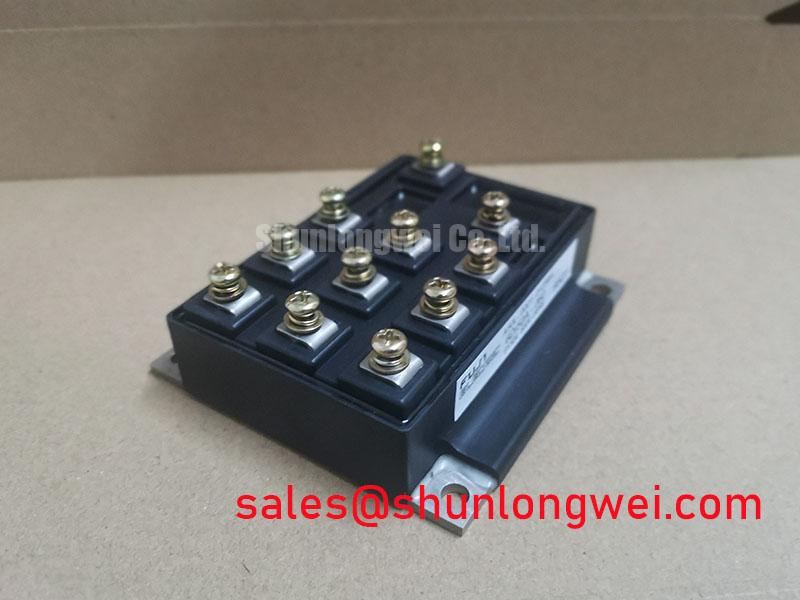
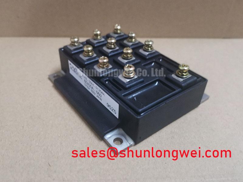
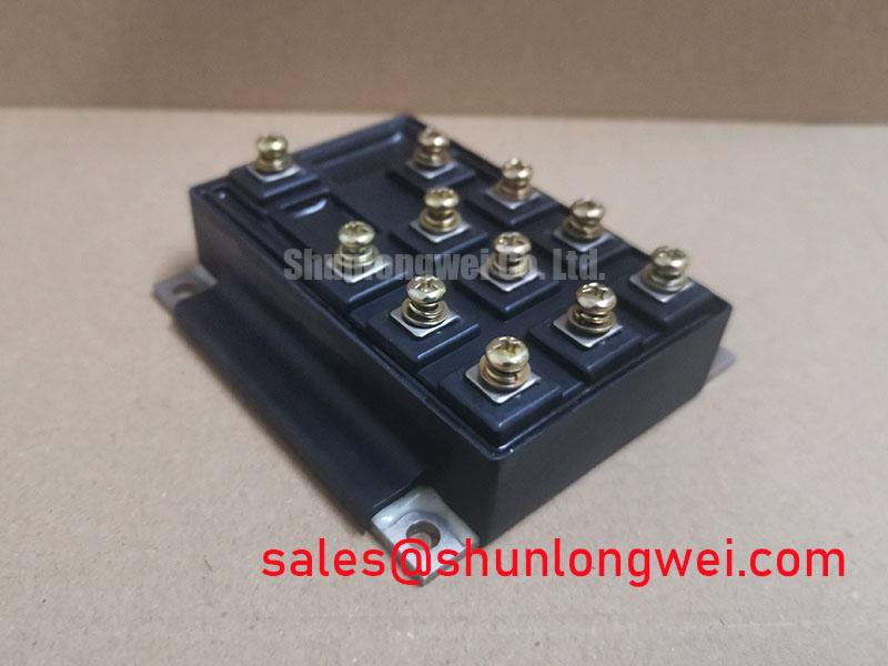
The 6DI50A-60 is a bipolar power transistor module, rather than an IGBT module. Its listed ratings are 600 V and 50 A. These ratings identify the device class; consult the manufacturer’s datasheet for the applicable rating definitions, conditions, and safe operating area. Actual operation also depends on switching conditions, thermal management, base-drive behavior, and the surrounding power circuit.
Separate the base-driver emitter return from the high-current emitter route when laying out the switching stage. The power emitter path carries rapidly changing load current, while the driver return should provide a quieter reference for the base signal. If both paths share a long copper section, the voltage developed by stray inductance can appear directly in the base-drive loop and may promote oscillation or unintended conduction.
Keep the base-drive loop compact and physically separated from the collector and load-current paths. A symmetrical arrangement between complementary switching devices helps keep commutation behavior consistent, but symmetry should be judged by the complete current loop rather than by component placement alone. The DC-link capacitor, module terminals, bus structure, and return conductors all influence the switching loop.
During commissioning, inspect the base-to-emitter waveform at the module rather than at the distant driver connector, and check base current where practical. Compare the turn-on and turn-off behavior of complementary devices under the same operating condition. Ringing that appears only after the power stage is connected may indicate coupling through the shared return, bus structure, or probe connection. Use appropriately rated differential or isolated measurement equipment with a short, low-inductance connection, and verify that the observed waveform is not created by the test setup.
Design Consideration: maintain suitable creepage, clearance, and copper spacing around high-voltage switching nodes according to the system insulation class and applicable safety standard. The exact spacing is determined by working voltage, pollution environment, material group, altitude, and enclosure construction, not by the module rating alone.
Field Diagnostics & Commissioning: Dynamic Power Loss Dissipation and Multi-RC Thermal Modeling in 6DI50A-60 Topologies
Evaluate pulsed thermal stress through the complete junction-to-case path rather than relying only on the steady-state heatsink temperature. A multi-RC thermal model can represent the transient response from the semiconductor junction to the case and then through the thermal interface and heatsink. For a pulsed overload, the resulting peak junction estimate should be compared with the device thermal boundary and the system protection response. The pulse must also remain within the applicable safe operating area; a thermal estimate alone does not establish safe operation for a bipolar transistor.
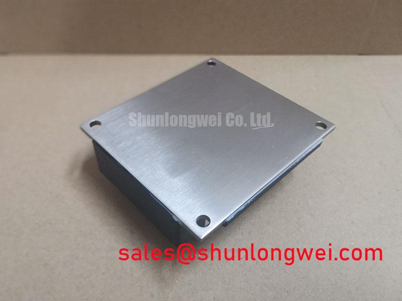
The thermal interface must be continuous and free from voids, contamination, or excessive compound. The mounting surface should be flat, clean, and mechanically stable before the module is tightened. Mounting torque is a Design Consideration governed by the module construction, fastener size, heatsink material, washer arrangement, and the manufacturer’s mechanical instructions; it should not be substituted with a generic value.
Power loss evaluation should include conduction loss, switching loss, pulse duration, repetition rate, and the actual cooling condition. A short overload can produce a significant junction temperature excursion even when the heatsink feels cool. Record case temperature near the module mounting area and correlate it with base-drive timing, collector-emitter voltage, and load current during controlled commissioning.
Dead-time must prevent simultaneous conduction of complementary devices while avoiding excessive distortion of the commanded waveform. The appropriate buffer is system-determined by driver propagation delay, transistor storage and fall times, temperature, load current, base-drive conditions, and drive-loop parasitics. Place the complementary drive paths so that their return currents do not share an uncontrolled impedance, then validate the interlock using isolated voltage and current measurements.
| Part | Manufacturer | Rated Voltage | Rated Current | Package |
|---|---|---|---|---|
| 6DI50A-60 | Fuji Electric | 600 V | 50 A | Power Transistor Module |
| 6DI50AH-050 | Fuji Electric | Consult Datasheet | Consult Datasheet | Consult Datasheet |
The comparison above is for sourcing orientation only. A replacement decision requires confirmation of terminal arrangement, base-drive requirements, thermal interface, mechanical dimensions, protection coordination, and switching performance in the target assembly.
6DI50A-60 Circuit Protection & Reliability: Separating Driver Return from Main Current
Identify the main load emitter terminal and check the module’s terminal diagram for any separate auxiliary emitter connection before routing the PCB. If a dedicated driver-return terminal is provided, use it as specified by the manufacturer. Otherwise, route the driver return separately to the appropriate emitter connection, minimizing shared impedance with the load-current loop. Shared impedance can create di/dt-induced voltage movement that disturbs the base drive.
For a motor actuator, inspect the base-drive waveform during acceleration, deceleration, current reversal, and regenerative operation. A stable signal at low load does not establish stability during commutation. If the base-drive waveform shifts with load current, examine the return routing, busbar geometry, driver supply decoupling, and probe reference before changing base-drive resistance or current.
Protection coordination should include the semiconductor fuse or electronic current limiter, short-circuit detection response, and the permissible energy of the complete power path. Fast-fuse selection should consider the actual fuse curves and let-through I²t, wiring impedance, and pulse profile, together with the module’s documented safe operating area and any specified short-circuit limits. An I²t comparison alone does not establish transistor protection. Do not infer a safe short-circuit duration from the 50 A rated current.
For physical installation, 💡 Pro Tip: disconnect the DC link and verify the absence of stored energy before inserting, removing, or attaching probes to the module connections.
For background on IGBT technology, engineers can consult The Ultimate IGBT Knowledge Base; IGBT gate-drive guidance does not directly apply to this bipolar transistor module. Fuji Electric’s broader semiconductor information is available through its Power Semiconductor and IPM Modules resource and its PIM 7-Pack information. These resources do not establish the specifications or compatibility of the 6DI50A-60. When evaluated in precision stepper or BLDC servo motion actuators, the 6DI50A-60 should be validated as part of the complete base-drive, thermal, busbar, and protection system.