Content last revised on September 10, 2026
2MBI300VH-120-55 Fuji Electric 1200 V 300 A IGBT Module
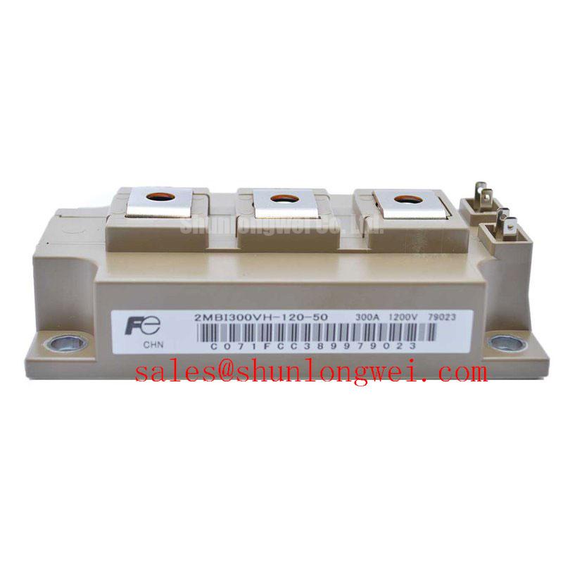
Begin incoming inspection by confirming the 2MBI300VH-120-55 marking, checking the module body for visible mechanical damage, and verifying the nameplate ratings before connecting any test equipment. The stated manufacturer is Fuji Electric, with an official rated voltage of 1200 V, an official rated current of 300.0 A, and a Module package.
| Parameter | Specification | Classification |
|---|---|---|
| Manufacturer | Fuji Electric | Product identification |
| Model | 2MBI300VH-120-55 | Product identification |
| Rated voltage | 1200 V | Official Specification |
| Rated current | 300.0 A | Official Specification |
| Package | Module | Official Specification |
2MBI300VH-120-55 Circuit Protection and Reliability: Calibrating Thermal Paste Degradation Prevention and Mounting
For a high current module, the thermal interface is part of the electrical reliability assessment. A thin, continuous layer of suitable thermal interface material should cover the intended contact area without dry zones, trapped contamination, or visible air pockets. A general Design Consideration is to control the applied TIM thickness within the system supplier’s specified process window, commonly evaluated around 50 to 100 µm where the heatsink and interface system support that range. The final value remains dependent on surface finish, flatness, material type, and the approved assembly process.
Inspect the heatsink for burrs, local distortion, and contamination before positioning the module. If baseplate curvature or uneven contact is suspected, engineers should verify the contact pattern using the approved workshop method rather than increasing screw force. Sequential tightening across the mounting points helps distribute pressure, but the correct screw torque must come from the Fuji Electric mechanical documentation or the equipment manufacturer’s assembly drawing. Clearance around power terminals should also be checked against the busbar, creepage, and service-access requirements of the complete inverter.
In commercial string inverters and micro-grid energy storage equipment, thermal troubleshooting should compare heatsink temperature, phase current, switching waveform, and the condition of the interface material. A rising case temperature may involve airflow, clamping, switching loss, current imbalance, or sensor placement, so the investigation should not assign a single cause without measurement.
2MBI300VH-120-55 Operational Boundaries: Evaluating Static and Dynamic Current Distribution
The 1200 V voltage rating and 300.0 A current rating are Official Specification values, not a complete operating prescription for a converter. Actual allowable current depends on switching frequency, duty cycle, case temperature, cooling capability, gate drive conditions, and the limits stated in the applicable datasheet. Designers should verify the DC link and braking resistor energy path before evaluating this module in regenerative braking choppers or battery charge and discharge stages.
As a general Design Consideration, the positive temperature coefficient often associated with IGBT conduction voltage can assist steady-state static current sharing between suitably matched devices. Dynamic sharing is more sensitive to gate loop inductance, driver propagation delay, stray capacitance, and layout symmetry. Use equal-length gate paths where the circuit topology requires parallel devices, and verify turn-on and turn-off behavior with current probes and an oscilloscope.
Dead-time should provide a system-determined buffer that prevents complementary switches from conducting simultaneously while avoiding unnecessary freewheel-diode conduction. The correct interval depends on the selected driver, isolation device, gate resistance, temperature, and measured switching delay. Industrial drive boards should also assess the isolator’s common-mode transient behavior during rapid DC-link transitions rather than treating the optocoupler or digital isolator as an independent EMC certification.
Transient Dynamics and Electrical Design: Evaluating Thermal Capacitance During Pulsed Operation
Brake chopper service and micro-grid storage converters can impose short energy pulses followed by recovery periods. The junction-to-case thermal response should therefore be evaluated with the manufacturer’s transient thermal impedance data and the actual pulse width, repetition pattern, heatsink condition, and cooling airflow. A multi-RC thermal model can estimate junction temperature by accumulating each pulse’s thermal response, but the result is an Engineering Calculation and must be checked against measured case temperature and switching loss.
When a turn-off waveform shows excessive collector voltage overshoot, minimize the commutation loop parasitic inductance and inspect the DC-link capacitor connection, busbar geometry, gate resistance, and clamp network. The Miller plateau is influenced by collector voltage slew and reverse transfer capacitance, commonly denoted Cres in power semiconductor documentation. Active clamping may be evaluated where the driver and protection topology support it, with the clamp threshold and response verified against the module’s published electrical limits.
For bidirectional DC to DC battery systems, thermal cycling should be assessed across both charge and discharge directions. Engineers should log current, case temperature, switching transitions, and cooling response during representative load profiles. No field lifetime figure should be assigned without an authoritative test method, mission profile, and source document.
Preventing Spurious Faults: Differential Gate Source Loop Routing Guidelines
Gate control should reference the emitter return used by the driver, while the high-current emitter path should be kept separate whenever the module and schematic provide a suitable auxiliary control return. Shared copper can introduce emitter mutual coupling, allowing load current transients to disturb the gate signal and produce ringing or false turn-on. The terminal assignment must be confirmed from the original Fuji Electric documentation; this page does not establish an unverified pinout.
Route the gate and return as a compact differential loop, keep it away from high di/dt commutation paths, and place the driver protection components according to the validated board layout. If a fault appears only during switching, compare the gate voltage at the module terminals with the driver output and inspect the collector-emitter waveform at the same time. This can reveal impedance mismatch, isolation disturbance, or parasitic coupling without assuming that the IGBT alone is defective.
💡 Bench Tip: Perform cold-state diode-mode comparisons only with the module isolated from the circuit, use ESD protection, and compare every reading with a known-good reference assembled under the same test conditions.
Engineers evaluating a related Fuji Electric option can review 2MBI300U4H-120-50 as a separate replacement reference, subject to confirming voltage, current, gate characteristics, mechanical fit, terminal arrangement, and thermal requirements. For switching-loss and industrial-drive context, consult Unlocking Efficiency in Industrial Drives and Fuji Electric’s Brake Chopper IGBT Modules information.