


Content last revised on March 24, 2026
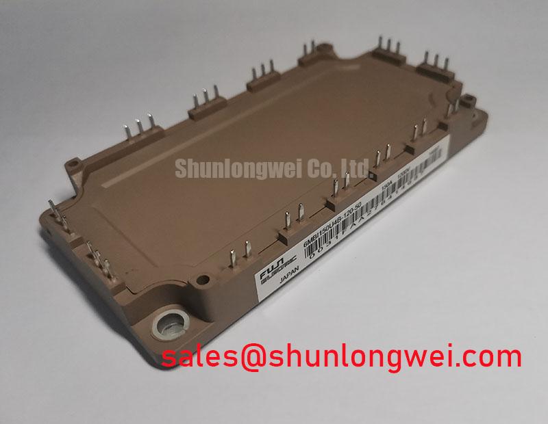
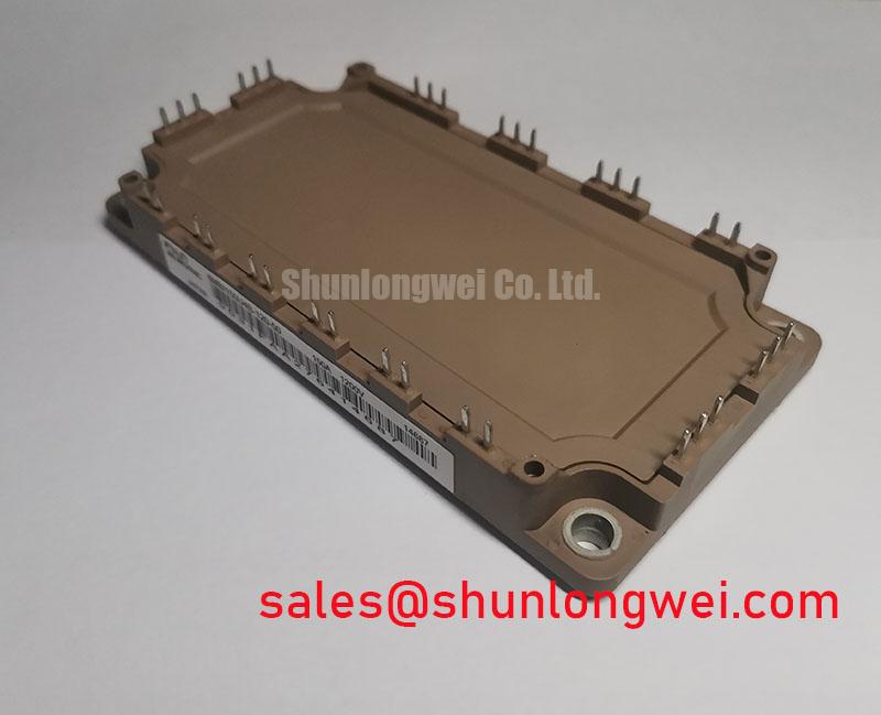
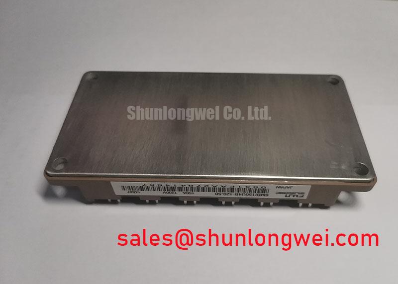
6MBI150U4B-120-50 | 1200V 150A 6-Pack IGBT Module for High-Efficiency Inverters
Executive Summary: Key Performance Highlights
Engineered to minimize total power loss in high-frequency switching applications, the Fuji Electric 6MBI150U4B-120-50 is a 1200V, 150A 6-in-1 IGBT module. It integrates a full three-phase inverter bridge into a single, compact package, delivering key specifications of 1200V | 150A | VCE(sat) 1.80V (typ). This module's primary engineering benefits include significantly reduced thermal management requirements and the ability to design systems with higher power density. By balancing low conduction losses with optimized turn-on/turn-off characteristics, it provides a direct solution for improving efficiency in demanding power conversion systems.
Application Scenarios & Value
System-Level Benefits in Motor Drives and Power Converters
For motor drives up to 75kW operating at higher PWM frequencies, this module offers a superior balance of efficiency and thermal performance. A primary challenge for engineers designing Variable Frequency Drive (VFD) systems is increasing the switching frequency to reduce audible motor noise and shrink the physical size of output filter components. However, higher frequencies typically lead to greater switching losses and increased thermal stress. The 6MBI150U4B-120-50 directly addresses this trade-off. Its 4th Generation U-series chip technology is specifically optimized to reduce turn-on (Eon) and turn-off (Eoff) losses. This allows designers to push the PWM frequency higher, achieving quieter operation and a more compact system footprint without compromising thermal stability.
This module's integrated 6-pack configuration streamlines the design and assembly of the entire three-phase inverter power stage. What is the main benefit of its integrated 6-pack design? Simplified assembly of three-phase inverter stages. This reduces component count, minimizes parasitic inductance compared to discrete solutions, and simplifies the overall bill of materials (BOM). Applications that benefit from this optimized performance include general-purpose inverters, servo drives, and uninterruptible power supplies (UPS) where efficiency and reliability are paramount. For systems requiring higher current handling, the related 2MBI200NB-120 offers a 200A capability in a similar voltage class.
Key Parameter Overview
Decoding Key Specifications for High-Frequency Design
The performance of the 6MBI150U4B-120-50 is defined by a set of electrical and thermal parameters critical for system design and simulation. The table below outlines the key specifications derived from the official datasheet, grouped by function to aid in engineering evaluation.
| Parameter | Symbol | Condition | Value |
|---|---|---|---|
| Absolute Maximum Ratings (Tj = 150°C) | |||
| Collector-Emitter Voltage | Vces | - | 1200V |
| Gate-Emitter Voltage | Vges | - | ±20V |
| Continuous Collector Current | Ic | Tc = 25°C | 200A |
| Continuous Collector Current | Ic | Tc = 80°C | 150A |
| 1ms Collector Current Pulse | Icp | - | 300A |
| Electrical Characteristics - IGBT (Tj = 25°C) | |||
| Collector-Emitter Saturation Voltage | VCE(sat) | Ic = 150A, Vge = 15V | 1.80V (Typ) / 2.20V (Max) |
| Turn-on Switching Loss | Eon | Vcc=600V, Ic=150A, Vge=±15V | 21.0 mJ (Typ) |
| Turn-off Switching Loss | Eoff | 26.0 mJ (Typ) | |
| Reverse Recovery Loss | Err | 14.0 mJ (Typ) | |
| Thermal Characteristics | |||
| Thermal Resistance (IGBT) | Rth(j-c) | Junction to Case | 0.14 °C/W (Max) |
| Thermal Resistance (FWD) | Rth(j-c) | Junction to Case | 0.25 °C/W (Max) |
Download the 6MBI150U4B-120-50 datasheet for detailed specifications and performance curves.
Technical Deep Dive: Industry Insights & Strategic Advantage
Strategic Advantage in Energy-Efficient Power Systems
The drive for higher efficiency in power electronics is propelled by both economic and regulatory pressures. Standards such as thermal management and energy efficiency classifications for motors (IE3/IE4) compel designers to minimize every watt of power loss. The 6MBI150U4B-120-50 serves as a critical enabling component in this landscape. Its low VCE(sat) is a key factor in reducing conduction losses, which are dominant in lower-frequency applications. You can think of VCE(sat) as a form of electrical friction; a lower value means less energy is converted into waste heat when the switch is fully on, much like a well-lubricated bearing minimizes mechanical friction. This directly results in a cooler-running module and reduces the burden on the cooling system.
Simultaneously, the module's optimized switching energy (Ets) is crucial for systems operating at higher frequencies. What defines the 6MBI150U4B-120-50's performance? A balance between low conduction and switching losses. This balanced design ensures that as designers increase PWM frequencies to gain system-level benefits—like reduced motor hum or smaller magnetics—the module's efficiency does not collapse due to excessive dynamic losses. This capability is fundamental to creating power conversion systems that are not only efficient but also compact, quiet, and cost-effective over their operational lifetime.
Frequently Asked Questions (FAQ)
How does the typical VCE(sat) of 1.80V on the 6MBI150U4B-120-50 impact the thermal design of an inverter?
A lower VCE(sat) directly reduces the power dissipated as heat during the IGBT's on-state (P_cond = VCE(sat) * Ic). With a typical VCE(sat) of 1.80V at its nominal 150A rating, this module generates less heat compared to older generation IGBTs with VCE(sat) values well above 2.0V. This reduction in heat load allows for the use of smaller, lighter, and more cost-effective heatsinks, or alternatively, provides greater thermal margin for operating in high ambient temperatures, enhancing overall system reliability.
What is the primary advantage of using a 6-pack module like the 6MBI150U4B-120-50 compared to discrete IGBTs?
The primary advantage is system integration and simplification. A 6-pack module contains all six IGBTs and their corresponding freewheeling diodes required for a three-phase inverter bridge in a single, thermally optimized package. This significantly simplifies the PCB layout, reduces assembly time and cost, and minimizes stray inductance between switches, which can improve switching performance and reduce voltage overshoots. For more information, refer to this guide on decoding IGBT datasheets.
What does the 'U4' designation in the part number signify for Fuji Electric IGBTs?
The "U4" denotes Fuji Electric's 4th Generation "U-series" IGBT chip technology. This series is specifically engineered to provide a soft-switching characteristic with an optimal balance between low collector-emitter saturation voltage (VCE(sat)) for reduced conduction losses and minimized switching losses (Eon/Eoff). This makes it particularly well-suited for high-frequency hard-switching applications like motor control and UPS systems, where both static and dynamic losses contribute significantly to overall system inefficiency.
Final Engineering Perspective
The 6MBI150U4B-120-50 is a highly integrated power module designed for engineers who need to maximize the efficiency and power density of three-phase inverter systems. Its balanced electrical characteristics provide a robust foundation for developing next-generation power converters that meet stringent performance and size requirements. To further evaluate its suitability for your specific application, review the detailed performance curves in the official datasheet and consider its thermal behavior within your system's operational envelope.