


Content last revised on April 14, 2026
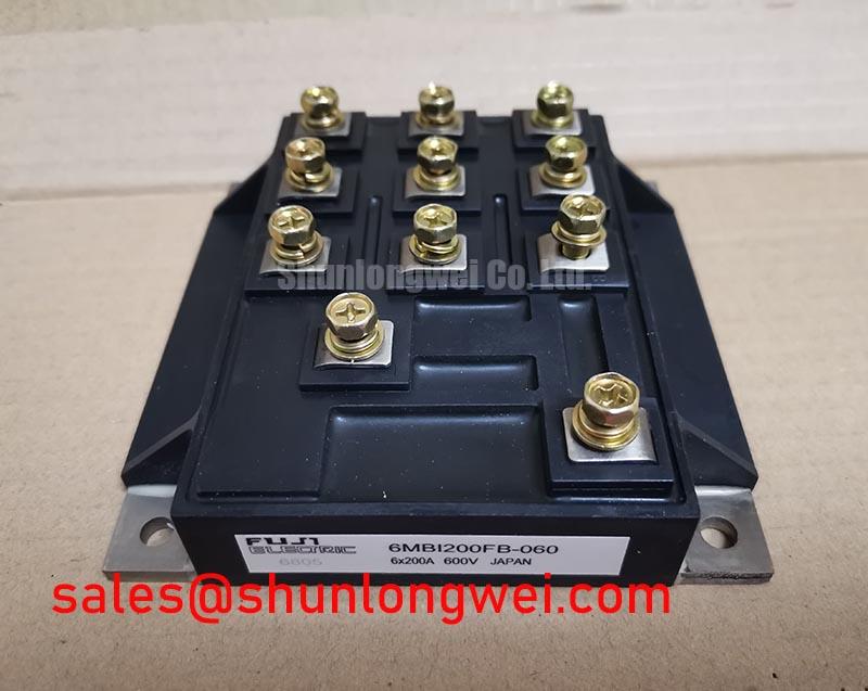
6MBI200FB-060 Fuji Electric IGBT Module: Technical Analysis for High-Efficiency Inverter Design
Introduction: A Detailed Engineering Overview
The Fuji Electric 6MBI200FB-060 is a high-integration IGBT module designed to deliver robust performance in medium-power three-phase inverter systems. This component combines six 600V IGBTs with corresponding free-wheeling diodes into a single, thermally efficient package, engineered to streamline both the design and manufacturing of motor drives and power converters. Key specifications include: 600V | 200A | VCE(sat) 2.7V (max). The module offers the core benefits of simplified system assembly and optimized switching performance. This integrated approach directly addresses the engineering challenge of minimizing stray inductance and improving the reliability of the power stage. For VFD designs up to 75kW on 240V AC lines, the 6MBI200FB-060's balanced switching characteristics offer an optimal path to high efficiency.
Key Parameter Overview
Decoding the Specs for Efficient Power Conversion
The technical specifications of the 6MBI200FB-060 are tailored for applications where efficiency and thermal stability are critical. The parameters below highlight its capacity for handling substantial power while maintaining controlled switching behavior, a crucial factor in modern power electronics.
| Parameter | Symbol | Value | Conditions |
| Collector-Emitter Voltage | VCES | 600 V | VGE = 0V |
| Gate-Emitter Voltage | VGES | ±20 V | |
| Continuous Collector Current | IC | 200 A | TC = 80°C |
| Max. Power Dissipation | PC | 780 W | Per IGBT |
| Collector-Emitter Saturation Voltage | VCE(sat) | 2.7 V (Max) | IC = 200A, VGE = 15V |
| Operating Junction Temperature | Tj | +150 °C |
Download the 6MBI200FB-060 datasheet for detailed specifications and performance curves.
Application Scenarios & Value
Achieving System-Level Benefits in Industrial Motor Control
The 6MBI200FB-060 is engineered primarily for three-phase power conversion applications, where its integrated 6-in-1 topology provides significant design advantages. What is the key benefit of the 6-in-1 topology? It significantly simplifies inverter design and assembly.
- Variable Frequency Drives (VFDs): In VFD systems for controlling industrial AC induction motors, the module's 200A rating is suitable for applications in the 50 to 75 kW range (on 240V AC lines). Its integrated nature reduces the complexity of power stage layout, minimizes parasitic inductance that can cause voltage overshoots, and simplifies the heatsink design and mounting process.
- Servo Drives: For high-performance robotics and CNC machinery, precise motor control is paramount. The module's fast-switching FWDs and controlled IGBT characteristics enable the high-frequency Pulse Width Modulation (PWM) schemes necessary for smooth torque delivery and accurate positioning.
- Industrial Power Supplies: In high-power Switched-Mode Power Supplies (SMPS) or Uninterruptible Power Supplies (UPS), the module can serve as the core of a robust inverter stage, ensuring reliable AC output under demanding load conditions.
In a typical VFD application, engineers face the challenge of managing both conduction and switching losses. The 6MBI200FB-060's VCE(sat) of 2.7V (max) dictates the conduction losses, while its specified turn-on and turn-off times are critical for calculating Switching Loss. This balance is key to achieving high operating efficiency and minimizing thermal stress on the entire system. For applications requiring higher voltage blocking, such as those on 480V AC lines, a 1200V-class module like the 6MBI450U-120 would be a more suitable component for evaluation.
Frequently Asked Questions (FAQ)
What is the primary advantage of the integrated 6-in-1 configuration in the 6MBI200FB-060?
The main benefit is system simplification. By integrating all six IGBTs and their corresponding freewheeling diodes for a three-phase bridge into one package, it reduces component count, simplifies PCB layout, lowers assembly costs, and minimizes stray inductance between switches, leading to improved electrical performance and reliability.
How does the VCE(sat) of 2.7V impact system design?
The Collector-Emitter Saturation Voltage (VCE(sat)) is the on-state voltage drop across the IGBT. A value of 2.7V at 200A is a primary determinant of conduction losses (Power Loss = VCE(sat) * IC). This figure is critical for thermal management calculations, as it directly influences the amount of heat the module will generate and thus the size and type of heatsink required to keep the junction temperature within safe limits.
Is an external freewheeling diode required for use with inductive loads?
No, the 6MBI200FB-060 includes a co-packaged, optimized freewheeling diode (FWD) for each IGBT. These diodes are essential for applications with inductive loads, such as electric motors, as they provide a safe path for the inductor current to flow when the IGBT is switched off, protecting the transistor from potentially damaging voltage spikes.
What considerations are important for the gate drive circuit for this module?
A proper gate drive circuit should provide the recommended gate-emitter voltage (typically +15V for turn-on, 0V or a negative voltage for turn-off) with sufficient peak current to charge and discharge the IGBT's input capacitance quickly. This ensures the device switches efficiently, minimizing switching losses. The datasheet provides gate charge (QG) values that are essential for selecting or designing an appropriate gate driver IC.
Technical Deep Dive
Analyzing Switching Characteristics for Loss Reduction
A critical aspect of inverter design is minimizing power loss, which occurs during both the on-state (conduction loss) and the transition between states (switching loss). While VCE(sat) governs conduction losses, the switching performance of the 6MBI200FB-060 is defined by parameters like turn-on time (ton) and turn-off time (toff). The datasheet specifies typical values of 0.4 µs and 0.5 µs, respectively. Think of this like a water valve: the faster you can fully open or close it, the less time is spent in a partially open state where flow is restricted and energy is wasted as turbulence. Similarly, the faster an IGBT transitions, the less time it spends in the high-dissipation active region, reducing the energy lost as heat during each switching event. For a system using a 10 kHz PWM frequency, the IGBTs switch 20,000 times per second (on and off). Even a small reduction in energy loss per switch, achieved through these controlled switching times, compounds into significant gains in overall inverter efficiency and a reduced thermal load on the cooling system.
This strategic focus on providing a complete, tested three-phase solution allows designers to accelerate development and focus on higher-level system control and optimization. By leveraging the integrated nature and predictable performance of the 6MBI200FB-060, engineering teams can achieve a more compact and reliable power stage, a key competitive advantage in the industrial automation and power conversion markets. For more information on Fuji Electric's portfolio, visit their power module product page.