

Content last revised on September 10, 2026
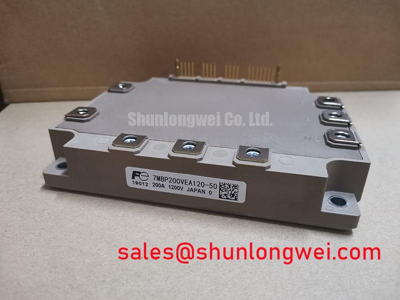
Preventing Spurious Faults: Atmospheric Neutron Radiation Impact on 7MBP200VEA120-50
Atmospheric neutron effects, altitude-related cooling changes, and single-event failure mechanisms require device-specific qualification data. No FIT rate, Single Event Burnout limit, or altitude derating value is established by the supplied product parameters, so these figures must not be assigned to this module without an authoritative Fuji Electric source or a qualified reliability study. A design consideration for equipment operating above typical factory-floor elevations is to verify the actual DC-bus voltage, switching transients, insulation coordination, cooling performance, and enclosure pressure or contamination controls under site conditions.
During a field failure, record the DC-link voltage and inspect the gate-driver supply, current feedback, and fault history before removing the module. Compare cold-state terminal impedance with a known-good unit only as a screening step; a reading outside expectation may indicate damage elsewhere in the commutation path and is not, by itself, proof of a neutron-related event. Keep high-voltage routing, control wiring, and sensor returns arranged to limit unwanted coupling, then validate the assembled inverter with appropriate surge and switching tests. The Unlocking Efficiency in Industrial Drives article can provide broader power-drive design context, but it does not replace model-specific ratings.
7MBP200VEA120-50 Operational Boundaries: Evaluating DC-Bus Low-Inductance Laminated Busbar Design Limits
Inspect the positive and negative DC-link paths for balanced geometry, loose fasteners, excessive loop area, and degraded film capacitors. During turn-off, stray inductance combines with current slew to create an overvoltage above the DC bus. The engineering relationship is commonly expressed as the peak voltage being the DC voltage plus the inductive contribution from stray inductance and current change rate. The acceptable peak must be verified against the module’s official switching and blocking limits; a target such as a particular nanhenry value is a system design objective, not an available factory specification for this product.
Use a laminated busbar or another low-loop-area arrangement where practical, place commutation capacitors close to the power terminals, and evaluate the complete assembly with a properly compensated high-voltage probe. MOVs can support overvoltage absorption at the DC-link or input interface, but their clamping behavior, energy rating, leakage, and coordination with fuses must be selected from the system transient study. A snubber capacitor may reduce a measured spike, yet excessive capacitance can increase switching loss and circulating current. Switching frequency, ambient temperature, airflow, and heatsink condition must therefore be assessed together rather than assigned from the module’s 1200.0 V and 200.0 A identification alone.
Preventing Spurious Faults: Thermal Interface Material Thickness Uniformity Guidelines for 7MBP200VEA120-50
Before installation, clean both mating surfaces using a process approved for the heatsink and module materials, and check the baseplate and heatsink for burrs, embedded debris, or visible curvature. Apply the selected thermal interface material as a continuous, controlled layer that fills surface irregularities without creating an unnecessarily thick thermal barrier. The supplied data does not specify a TIM thickness, void limit, baseplate flatness, or mounting torque for this model, so those values must come from the mechanical datasheet and the heatsink manufacturer.
Mounting should bring the module down evenly so the interface material spreads uniformly. Use the specified screw sequence and calibrated tools, then recheck electrical clearances and terminal strain after the assembly has settled. In a bidirectional battery DC to DC charger or traction inverter, repeated charge and discharge cycles can expose weak thermal contact through changing case temperature and fault frequency. Record heatsink temperature, coolant or airflow condition, and phase-current balance during controlled testing rather than inferring junction temperature from housing temperature alone.
⚠️ Field Alert: Disconnect the DC link and verify its discharged state before inserting, removing, or tightening any module connection.
7MBP200VEA120-50 Circuit Protection & Reliability: Calibrating High-Speed Fault Management: VCE Desaturation
Desaturation protection, short-circuit response, gate clamping, and soft turn-off are functions of the gate-driver circuit unless the relevant datasheet explicitly states integrated protection. Do not assume that this module independently detects a short circuit or guarantees a response time such as ten microseconds. The driver designer should verify detection delay, blanking behavior, gate-loop inductance, fault reset logic, and the module’s specified short-circuit safe operating conditions through controlled testing.
For a suspected short-circuit event, first isolate the driver output and measure the gate-emitter path, then inspect the current sensor, desaturation diode path, soft turn-off network, and DC-link overshoot waveform. A two-stage turn-off approach can be considered when the measured inductive transient is excessive, but resistor, clamp, and timing values remain system-determined. The protection circuit should be validated at the highest intended bus voltage, temperature, load current, and switching condition. For coordinated front-end operation, engineers may examine the neutral reference page for the 2MBI200UB-120 as a related topology reference, without treating it as an automatic replacement or guaranteed companion device.