Content last revised on September 24, 2026
6MBP50RA060 Inspection and Verification
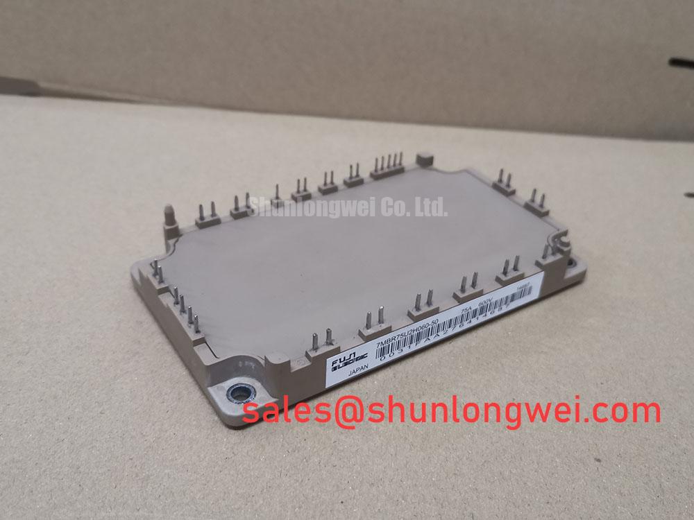
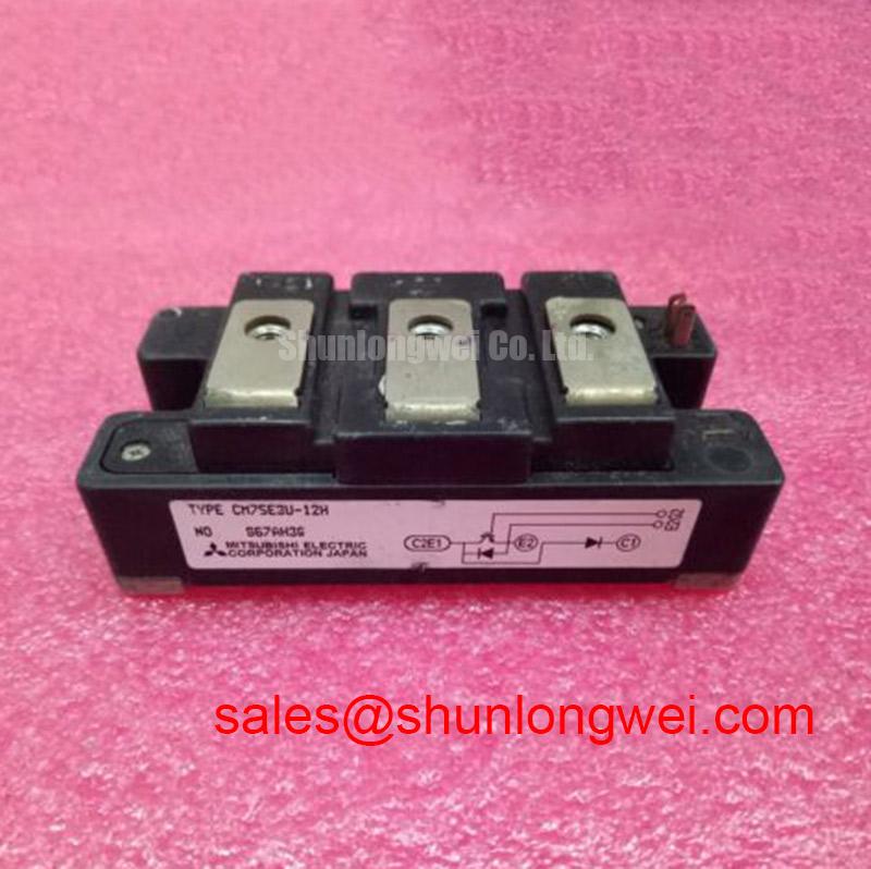
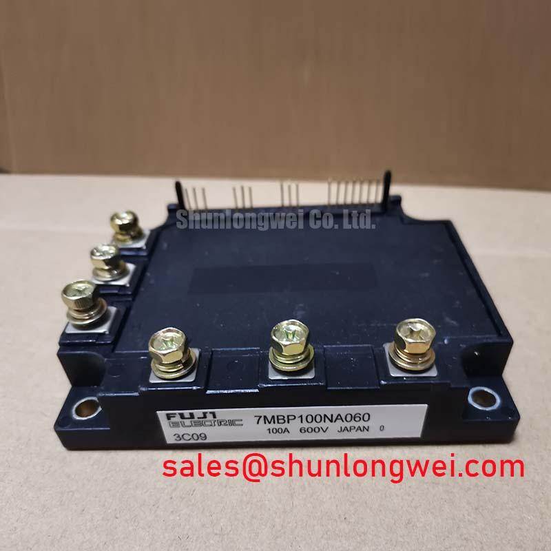
With the module isolated from the drive and the DC link confirmed discharged, begin by checking the terminal map against the original equipment documentation and comparing cold-state diode-mode readings across equivalent power paths. The 6MBP50RA060 from Fuji Electric is a 600V, 50A power module in a Module package. These are Official Datasheet Specifications and should be treated as the electrical identity to verify before any replacement evaluation in a servo amplifier or inverter assembly.
| Parameter | Specification | Classification |
|---|---|---|
| Manufacturer | Fuji Electric | Official product identification |
| Model | 6MBP50RA060 | Official product identification |
| Rated voltage | 600V | Official Datasheet Specification |
| Rated current | 50A | Official Datasheet Specification |
| Package | Module | Official Datasheet Specification |
Incoming inspection should start with the enclosure, terminals, locating features, and label condition, followed by resistance checks between control terminals and power terminals. A meter cannot qualify switching behavior, but it can reveal an abnormal short path or a terminal relationship that differs from the removed module. Where the original unit is available, record equivalent cold readings under the same meter range and probe polarity rather than relying on a generic diode-drop value.
💡 Bench Tip: Keep the module in an ESD-controlled work area, avoid touching signal terminals unnecessarily, and compare measurements only after both the replacement candidate and removed unit have reached the same ambient temperature.
6MBP50RA060 Circuit Protection & Reliability: Calibrating Active Miller Clamp Implementation
An active Miller clamp belongs to the gate-driver implementation, not to the published rating identity of the 6MBP50RA060. Before considering it, the technician should establish which terminals are gate-drive related from the original equipment schematic or module documentation. Do not infer gate and emitter relationships from package position alone. A mistaken connection during a powered diagnostic can create a destructive drive condition even when the module itself is electrically sound.
Design Consideration: during fast commutation, changing collector voltage can couple through a switching device’s gate capacitance and raise the off-state gate potential. If that coupled disturbance reaches the driver threshold region, unwanted conduction can occur. A low-impedance active clamp provides a controlled path that holds the commanded-off gate close to its reference during the vulnerable part of the switching event. Negative gate bias is also a system-level driver strategy sometimes evaluated where noise immunity requires it; its actual value, driver capability, isolation arrangement, and allowable gate limits must be verified against the applicable Fuji Electric documentation and the existing drive design.
For repair commissioning, inspect the gate-driver board before fitting a replacement module. Check for cracked driver isolation components, damaged gate resistors, lifted return traces, contaminated connector surfaces, and asymmetric channels. If the original board uses separate turn-on and turn-off paths, preserve that topology during repair. Substituting a resistor value or bypassing a failed clamp circuit without waveform testing changes switching conditions and should not be treated as a module-level correction.
When integrating this 600V module in a high-dynamics multi-axis CNC or robotics servo drive, engineers should verify dead-time behavior under the actual bus voltage and load condition. A gate command that appears clean at no load can behave differently when common-mode noise and load current are present. Use isolated probing and compare the gate-to-reference waveform with a known-good axis where practical.
The Fuji Electric Power Semiconductor and IPM Modules resource provides useful manufacturer-level context for power-module integration. For equipment where a different Fuji Electric module arrangement is being assessed, 7MBR50LC060 can be reviewed as a separate reference model, subject to a full verification of circuit topology, terminal arrangement, driver interface, thermal interface, and equipment documentation.
Field Diagnostics & Commissioning: High-Frequency Commutation Loop Inductance in 6MBP50RA060 Topologies
After static checks are complete, the next practical concern is the commutation loop formed by the module terminals, DC-link capacitor connections, bus structure, and measurement setup. During turn-off, the voltage seen by a switching path rises above the DC-link level by an amount related to loop inductance multiplied by the rate of current change. This is an Engineering Calculation principle, but the actual transient magnitude depends on the installed bus geometry, switching waveform, loading, probe placement, and driver behavior.
Design Consideration: minimize the physical area of the high-current commutation loop to suppress inductive overshoot. A compact, symmetric planar bus arrangement and local film-capacitor placement are commonly evaluated to contain parasitic inductance. The capacitor must be electrically close in the commutation path rather than merely nearby in the cabinet. Its capacitance, pulse-current capability, voltage class, and mechanical mounting should be selected by the system engineer after measuring peak switching stress.
For a field diagnosis, do not judge overshoot from a probe ground lead clipped across a long distance. That measurement arrangement can add its own loop and display ringing that is not present at the module terminals. Use an appropriate high-bandwidth differential measurement method and inspect voltage and current timing together. Repetitive ringing may indicate excessive bus-loop inductance, ineffective local decoupling, unsuitable gate-drive damping, or a measurement artifact; each possibility needs verification before modifying hardware.
Metal-oxide varistors and other surge-control parts may be present elsewhere in an industrial drive, but they do not replace a correctly controlled local commutation loop. Their coordination is a Design Consideration for the complete DC-link protection network. Engineers should verify clamping behavior against the actual supply, regenerative operating conditions, and measured switching peaks rather than assuming that a surge component protects every fast transient at the module.
In a broader conversion chain, a module such as 6MBI100L-060 may be evaluated as a separate power-stage element. It is not a presumed replacement or a guaranteed companion for the 6MBP50RA060; the original power schematic and control architecture determine whether any module is electrically relevant.
Preventing Spurious Faults: Transient Thermal Impedance Guidelines for 6MBP50RA060
A module can pass a cold diode-mode test and still require careful thermal-path evaluation before return to service. The published identity for this unit establishes 600V and 50A ratings, but it does not by itself define a permissible overload pulse, heatsink temperature, switching frequency, or complete inverter operating envelope. Those conditions are system-determined and should be verified from the relevant manufacturer documentation and original drive requirements.
Design Consideration: transient thermal impedance describes how junction temperature responds over time after a loss pulse. In engineering analysis, a multi-stage thermal model is often used to estimate the difference between a short pulse and a steady thermal load. The calculation requires credible loss data, duty cycle, switching conditions, case temperature, and thermal-interface assumptions. Without those inputs, assigning a junction-temperature margin from current rating alone would be unreliable.
During commissioning, monitor how the repaired axis behaves from cold start through normal loaded operation. Compare phase current balance, heatsink response, alarm history, and gate-drive waveform behavior with a healthy channel where the machine architecture permits it. Repeated thermal alarms may arise from several contributors, including restricted airflow, degraded heatsink contact, abnormal motor loading, control-loop instability, or switching stress. Isolate evidence before attributing the issue to the module.
Apply thermal interface material according to the equipment service procedure and keep mounting surfaces clean, flat, and free from trapped debris. The mounting sequence should bring the module base into even contact with the heatsink without twisting the housing. ⚠️ Field Alert: Do not energize a replacement module after changing its mounting arrangement until all power-terminal and control-terminal connections have been rechecked against the equipment documentation.
For equipment teams studying switching behavior in appliance-oriented resonant systems, the technical guide on Resonant Topologies in Home Appliances offers related context on topology-dependent switching stress. Its concepts should be adapted only after confirming that they apply to the actual servo-drive topology.
Assembly Integrity & Layout Architecture: Implementing Reinforced Insulation Barrier Integrity for 6MBP50RA060
Insulation coordination belongs to the complete drive assembly. The available Official Datasheet Specifications for the 6MBP50RA060 identify voltage rating, current rating, and package type, but they do not establish a published reinforced-isolation classification, a complete system creepage distance, or a common-mode transient immunity level for the surrounding gate-driver system. Those items must be verified using the module documentation, driver documentation, PCB layout, enclosure design, and the standards applicable to the finished equipment.
Design Consideration: preserve separation between high-energy power conductors and low-level control paths, especially where gate-driver return paths, current feedback wiring, encoder circuits, or communications cross the inverter area. A physical barrier, correctly rated isolated driver interface, disciplined cable routing, and clean board surfaces can reduce coupling paths that otherwise introduce false control signals. The required spacing is dependent on working voltage, pollution degree, material group, altitude, enclosure conditions, and the governing equipment standard.
During assembly inspection, look for displaced insulating sheets, damaged terminal covers, conductive debris, loose bus hardware, and control wiring that has migrated toward power conductors. Confirm that the module sits in the intended orientation and that every terminal connection matches the original drive drawing. If an isolation test is required by the equipment service process, use the specified test method and limits; an improvised high-voltage test can damage connected driver electronics or create misleading results.
For CNC and robotics servo repair, treat the module, driver board, DC-link assembly, heatsink, and feedback wiring as one controlled switching system. The 6MBP50RA060 is appropriately identified by its official 600V, 50A, and Module specifications, while successful integration depends on measured behavior and verification of the original equipment’s electrical, thermal, and isolation requirements.