

Content last revised on September 19, 2026
Assembly Integrity and Layout Architecture for the DC Link
For a high-dynamics multi-axis CNC drive or robotics servo, the module should be evaluated as part of the complete regenerative braking and motor-inverter power path. During deceleration, braking energy returns to the DC link and must be absorbed by the braking resistor and its switching circuit without exceeding the verified voltage boundary of the power stage. The 600 V rating of the 6MBP50NA060 is an official device parameter, not a complete system operating limit. The system engineer must verify the actual DC-link voltage, switching overshoot, protection threshold, and transient margin during controlled testing.
Keep the DC-link capacitor bank physically close to the high-current switching loop. A laminated or otherwise closely coupled busbar can reduce stray inductance compared with widely separated conductors. The practical objective is to shorten the commutation path, maintain a symmetrical current return, and limit the voltage overshoot produced when current changes rapidly. Engineers can assess the resulting peak with the relationship between DC-link voltage, loop inductance, and current slew rate, but the acceptable inductance and clamp level remain system-determined values rather than specifications of this module.
During field repair, check for darkened copper, lifted insulation, uneven busbar pressure, and signs of repeated braking stress. An oscilloscope measurement taken with an appropriate differential probe should compare the switch-node waveform with the DC-link voltage during acceleration, deceleration, and fault clearing. If the overshoot changes when the busbar is repositioned, the result may indicate a layout or commutation-loop issue rather than a defective module.
The front-end rectifier and the inverter or braking stage should be evaluated together. In a compatible topology, engineers may review the related 6MBI100L-060 as a complementary power-module reference, while confirming voltage, current, control timing, and mechanical compatibility from the original equipment documentation. The Fuji Electric Power Semiconductor and IPM Modules resource provides manufacturer-level context for the product family, but it does not replace the exact documentation required for the installed circuit.
Transient Dynamics and Gate-Control Integration
The gate-drive interface must be checked before a replacement is connected. Do not assume that a connector position, control polarity, or auxiliary terminal arrangement is identical to another module. Verify the original schematic, terminal markings, gate-emitter path, and driver supply sequence, then inspect the harness for insulation damage and intermittent crimp connections. A cold resistance comparison can identify an obvious abnormal path, but it cannot validate switching behavior or gate-drive timing.
Design Consideration: high common-mode voltage transitions can couple into the gate loop and create unwanted gate movement. A low-impedance gate loop, short return path, careful separation from high-current conductors, and an appropriately designed Miller-control strategy can reduce the risk of unintended turn-on. Negative gate bias may be considered in a system that supports it, but the allowable gate-emitter voltage, driver architecture, protection timing, and startup sequence must be verified from the applicable Fuji Electric documentation and the equipment design.
Active Miller clamping is a system-level gate-driver function, not an assumed feature of the 6MBP50NA060. When engineers evaluate this approach, they should confirm that the clamp operates only under the intended switching conditions and that it does not interfere with desaturation protection, short-circuit response, or gate discharge. The driver reference should be routed to the correct emitter reference used by the power loop; common-mode ground bounce can otherwise make a healthy signal appear unstable at the module terminals.
For servo drives that use regenerative braking, tune the gate waveform while monitoring collector-emitter voltage, gate-emitter voltage, phase current, and braking-resistor activity together. A ringing gate waveform may involve driver impedance, wiring inductance, probing technique, or switching interaction with another phase. Avoid diagnosing the module from one waveform alone. Compare all equivalent phase legs under the same test conditions and confirm that protective shutdown remains functional.
Thermal Interface and Mechanical Installation Control
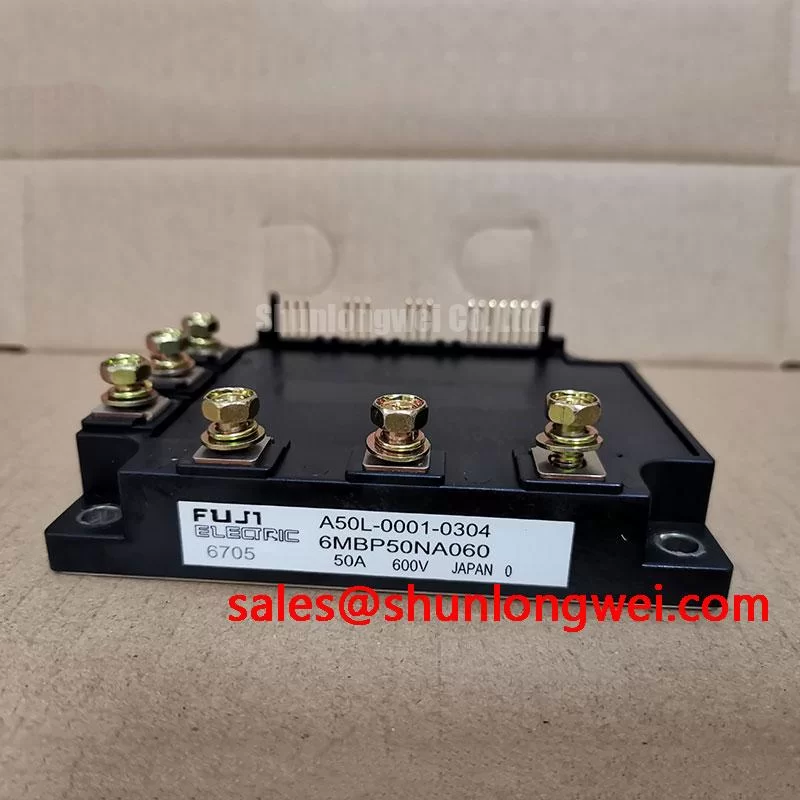
The 6MBP50NA060 is specified as a module package, while heatsink dimensions, baseplate flatness, thermal interface material, and mounting hardware belong to the equipment assembly. Before installation, clean the mating surfaces using the approved service process and check for burrs, contamination, or visible distortion. The heatsink should provide even support across the mounting area so that tightening does not load one corner of the module disproportionately.
Thermal interface material should be applied as a continuous, uniform layer appropriate to the selected material and surface condition. Excess compound can increase mess and complicate inspection, while incomplete coverage can create localized thermal resistance. The correct thickness is determined by the material supplier, surface flatness, and module mounting system; the module’s 600 V and 50 A ratings do not define a universal interface thickness.
Use the original equipment fastener specification and tighten progressively in the specified sequence. The final torque must come from the module documentation, fastener grade, and heatsink design rather than a generic value. After mounting, inspect the module seating, terminal alignment, busbar clearance, and cable strain relief. Vibration in CNC and robotic equipment can loosen an electrically sound installation if the busbar and cable support are not mechanically secured.
Field Alert: never connect or disconnect the gate-drive harness while the DC link or auxiliary control supply remains energized.
After installation, perform an insulation and continuity check appropriate to the equipment service procedure, followed by a controlled low-energy startup. Monitor heatsink temperature rise, phase-current symmetry, and fault history rather than relying only on the absence of an immediate alarm. The Field Engineer’s Handbook can support a structured inspection record for assembly, testing, and failure analysis.
Benchtop Waveform Tuning and Mismatch Diagnosis
Bench testing should begin with the electrical limits confirmed: 600.0 V rated voltage, 50.0 A rated current, and the required module package interface. These values identify the component’s stated rating; they do not authorize operation at those limits under every switching frequency, heatsink condition, duty cycle, overload event, or braking profile. Designers should establish operating margins from the complete thermal and electrical model, then validate them with measured waveforms.
When several parallel paths are used, static current sharing can benefit from the positive temperature behavior commonly associated with matched IGBT conduction characteristics, but dynamic sharing depends heavily on gate-loop symmetry, driver timing, emitter reference integrity, and commutation layout. Do not assume that equal cable lengths alone produce equal current. Compare collector-emitter voltage and current waveforms for each path, and investigate differences in gate amplitude, turn-off delay, ringing, or temperature before increasing load.
A mismatch between phases may originate in the gate driver, busbar geometry, current-sensor placement, DC-link impedance, or the module installation. Verify the measurement bandwidth and probe reference first, then repeat the test with identical loading and thermal conditions. For regenerative braking, observe the DC-link rise and braking-resistor command at the same time as the switching waveform. This helps distinguish control response from power-loop overshoot.
For a neutral cross-reference during procurement review, engineers may compare the application data of 7MBR50LC060, but substitution should be based on verified electrical ratings, terminal definitions, gate requirements, mechanical dimensions, thermal characteristics, and protection compatibility. The original equipment documentation remains the controlling reference for any replacement decision.