Content last revised on September 18, 2026
Assembly Integrity and Layout Architecture for PM20CVL060 Heatsink Contact Pressure
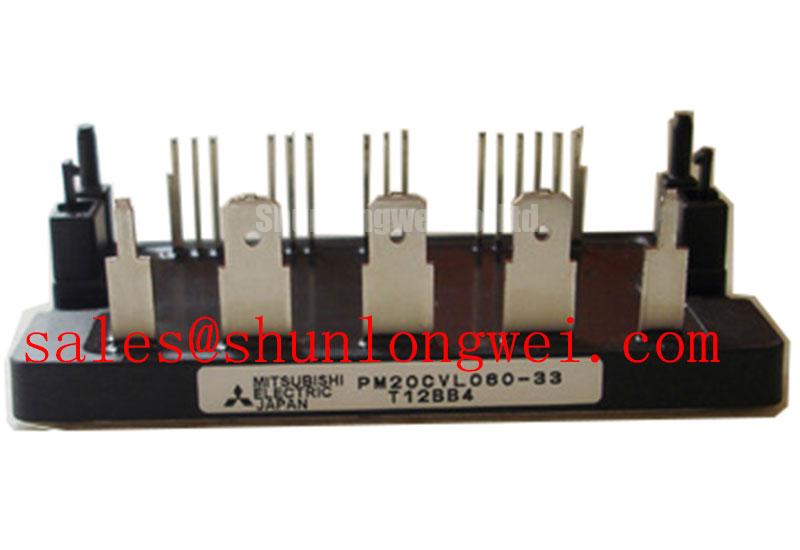
Before installing the PM20CVL060, isolate the drive from mains power, discharge the DC link according to the equipment procedure, and inspect the module baseplate, power terminals, control connector, and heatsink surface for contamination, distortion, corrosion, or uneven contact marks. The module is rated at 600 V collector emitter voltage and 20 A collector current as an Official Datasheet Specification, so replacement work should begin by confirming that the original drive operates within these electrical boundaries.
The Mitsubishi Electric PM20CVL060 is an intelligent power module intended to combine a power switching stage and protective functions within one package. Its specified 15 V control supply supports the module control interface, while integrated overcurrent, short circuit, overtemperature, and undervoltage protection reduce the amount of external protection circuitry required around the power stage. These functions must still be verified against the original controller wiring, fault logic, and restart behavior during commissioning.
| Official Specification | Value | Integration Relevance |
|---|---|---|
| Collector Emitter Voltage, VCES | 600 V | Appropriate voltage class for equipment connected to 200 V to 240 V AC supply systems, subject to measured DC link and transient conditions. |
| Collector Current, IC | 20 A | Applicable to compact motor power stages, including evaluations for loads up to approximately 1.5 kW where the complete thermal design supports operation. |
| Isolation Voltage, VISO | 2500 Vrms | Official isolation rating between the baseplate and terminals. |
| Control Supply Voltage, VD | 15 V | Specified supply requirement for the module control section. |
| Integrated Protection | OC, SC, OT, UV | Integrated protection functions for overcurrent, short circuit, overtemperature, and undervoltage conditions. |
Heatsink preparation is a practical reliability checkpoint. Remove aged interface residue without scratching either surface, then inspect the mounting land with a straightedge if uneven contact is suspected. A thin, controlled thermal interface material layer is a Design Consideration; the appropriate thickness depends on the materials, mounting flatness, and assembly method. Excess material can increase thermal resistance, while dry spots and trapped voids can concentrate heat beneath the module.
Use a sequential tightening pattern across the mounting points rather than fully tightening one side first. This helps distribute clamping load across the baseplate and compensates for minor heatsink flatness variation. The applicable screw size and tightening torque must be taken from the original equipment documentation or the applicable Mitsubishi Electric package documentation, because no mounting torque value is established here as an official specification for this specific part.
⚡ Safety Interlock Note: Do not connect or disconnect the PM20CVL060 control connector while the DC link remains energized, because stored energy and uncontrolled gate states can damage the drive stage.
Power and control routing should be treated as separate physical systems. Keep the control connector harness away from high current commutation paths, route fault return conductors with their associated reference paths, and preserve clearance required by the host equipment insulation design. When replacing a power stage board, technicians should compare terminal orientation, connector keying, mounting plane, and conductor spacing before applying power.
PM20CVL060 Thermal Electrical Optimization During Pulsed Motor Demand
For a precision stepper or BLDC servo motion actuator, thermal assessment should begin with the actual motion profile rather than nominal motor power alone. Acceleration, repeated positioning, holding torque, regenerative deceleration, ambient enclosure temperature, and heatsink airflow can each alter semiconductor heating. The 20 A collector current rating is an Official Datasheet Specification, but it does not replace system measurement of phase current, switching behavior, and case temperature under the intended duty cycle.
A transient thermal model is useful when current appears as short bursts rather than a steady load. Engineering Calculation can represent junction response through a multi resistance capacitance thermal network, where each thermal branch describes heat spreading over a different time interval. The resulting junction temperature estimate must use manufacturer thermal data for the installed module version, measured heatsink conditions, and the actual pulse energy. It should not be inferred from the current rating alone.
During commissioning, capture phase current, DC link voltage, heatsink temperature, and fault output at the same operating point. A rising case temperature may reflect inadequate thermal interface contact, reduced airflow, altered switching behavior, mechanical heatsink distortion, or a higher than expected load cycle. Comparing these observations with a known stable axis can help isolate whether the issue follows the module location, the motor cable, the controller command, or the mechanical load.
Freewheeling diode reverse recovery can influence switching overshoot and radiated noise in a motor inverter. The visible waveform depends on DC link placement, busbar geometry, motor cable characteristics, switching conditions, and the host control strategy. A snubber network is a Design Consideration that should be selected from measured ringing frequency and energy, then validated with voltage probes suitable for the observed transient environment. Adding a capacitor without checking its loop path can move resonance rather than solve it.
The module’s integrated OC, SC, OT, and UV protection supports fault handling, but the external controller should be checked for its response after a protection event. Verify fault latching, command inhibit behavior, controller reset sequence, and whether a restart command is possible only after the DC link and control supply have returned to the conditions specified by the equipment design. A semiconductor fuse and upstream protection coordination are system level Design Considerations; their interrupting behavior and energy capability must be evaluated against the actual DC link, wiring inductance, and available fault current.
Where a replacement assessment includes substantially different current classes or cabinet power levels, comparison should remain factual. The CM300DXDX1-24A belongs to a distinctly higher current category than the 20 A PM20CVL060. Terminal arrangement, gate drive requirements, thermal system, protection behavior, and circuit topology must be verified before either part is considered in an equipment repair decision.
Field Diagnostics and Commissioning with Symmetrical Planar Busbar Geometry
Before first energization, verify the module nameplate data, inspect the DC link capacitor connections, and confirm that the motor phases are routed to the intended terminals. The 600 V VCES rating provides the official voltage limit for the PM20CVL060, while the practical peak stress in an inverter also depends on commutation inductance and current slew rate. In engineering terms, peak voltage rises above the DC link voltage by the inductive contribution associated with loop inductance and the rate of current change. This relationship is a Design Consideration, not a declared transient operating allowance.
Low inductance DC link geometry is important because turn off current must transfer quickly between the module, local capacitor, and freewheeling paths. A planar, symmetrical arrangement places outgoing and return conductors close together, reducing loop area and helping suppress inductive overshoot. The final geometry must be determined by the host assembly, insulation distances, service access, current path, and oscilloscope verification of peak voltage margin during switching tests.
When inspecting an existing servo amplifier, look for long capacitor connections, asymmetric copper paths, loose fasteners, overheated lugs, or a DC link capacitor bank located remotely from the switching stage. These conditions may contribute to ringing, irregular fault trips, elevated conducted noise, or stress during rapid current transitions. They do not establish a single cause by themselves. A differential voltage measurement and phase current capture should be compared against the known operating waveform for the machine.
Control signal integrity also matters during fast switching. The 15 V control supply should be measured at the control interface under switching load, not only with the power stage idle. Supply disturbance, a damaged return path, insufficient isolation performance in the host driver board, or common mode coupling may interfere with command interpretation. The system integrator should assess isolator common mode transient immunity, supply decoupling, return routing, and controller fault timing as a complete circuit.
For broader background on switching mechanisms, protection boundaries, and power semiconductor behavior, consult The Ultimate IGBT Knowledge Base. Device level verification and measurement methods should also follow relevant industry test principles, including resources published by JEDEC Global Standards for the Microelectronics Industry.
Benchtop Waveform Tuning for Motor Cable Reflections at PM20CVL060
Long motor leads can create reflection behavior when the cable impedance and the connected motor impedance differ significantly. At the inverter terminals or motor terminals, this can appear as repeated ringing or voltage excursions that approach twice the inverter output step under unfavorable cable and switching conditions. The exact waveform depends on cable length, cable construction, motor winding characteristics, grounding arrangement, source impedance, and switching edge behavior. It must be measured rather than assumed.
Commissioning should begin at reduced system stress under the equipment manufacturer’s safe test procedure. Use an appropriately rated probe arrangement to inspect DC link voltage, phase voltage, and current during acceleration, constant speed, deceleration, and fault recovery. If reflections are visible, compare waveforms at the inverter output and at the motor end where access and safety procedures permit. This separates inverter commutation ringing from cable related reflection effects.
An output choke, sine filter, or dv/dt filter can be evaluated as a system level mitigation method when motor cable behavior requires it. Selection must consider the actuator control bandwidth, motor current waveform, resonant behavior, enclosure constraints, and thermal dissipation. Filter values and cable limits are determined by the complete servo system and must be validated through switching tests rather than copied from a generic inverter installation.
Regenerative deceleration should also be examined because a servo axis can return mechanical energy to the DC link. The braking chopper, braking resistor, DC link capacitor bank, and controller deceleration settings must be evaluated together. A DC link rise during braking may be associated with insufficient energy absorption, control configuration, mechanical inertia, or measurement location. The PM20CVL060 protection functions can respond to abnormal operating conditions, but they do not replace verification of the external regenerative energy path.
Gate related stress should be assessed through the host drive interface rather than assumptions about internal construction. Miller coupling can influence switching states when collector voltage changes quickly, especially where control return inductance or driver impedance has been altered during repair. Keep command and return routing compact, minimize shared inductance with power conductors, and verify switching behavior with the intended load. 💡 Pro Tip: Arrange DC link bus conductors symmetrically around the commutation loop and confirm turn off voltage margin with a double pulse test before releasing a revised drive board.