Content last revised on October 27, 2025.
MG15G6EL1 | 600V 15A IGBT Module for High-Efficiency Inverters
Product Overview: Balancing Speed and Integration
A Compact Six-in-One Solution for High-Frequency Power Conversion
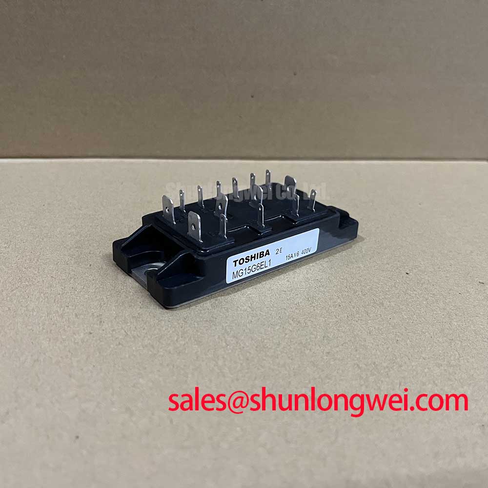
The Toshiba MG15G6EL1 is a highly integrated 6-in-1 IGBT module optimized for reducing switching losses in compact, high-frequency motor drives. It combines a robust electrical specification of 600V / 15A with an impressively fast fall time of 0.3 µs (max), directly addressing the core engineering challenge of efficiency in modern power electronics. This module's key benefits include enabling higher PWM frequencies and simplifying the layout of three-phase inverters. For low-power motor drives requiring PWM frequencies above 10 kHz, this module offers an optimal balance of integration and switching efficiency.
Application Scenarios & Value
System-Level Benefits in Compact Motor Drive Designs
The MG15G6EL1 is engineered for applications where power density and thermal performance are critical design constraints. Its primary value is delivered in low-power Variable Frequency Drives (VFDs), small robotic servo drives, and other compact motor control systems. In these environments, minimizing heat is paramount to achieving a smaller footprint and higher reliability.
Consider the challenge of designing a compact servo drive for an automated assembly line. High switching frequencies are needed for precise motor control, but this increases switching losses and, consequently, heat. The MG15G6EL1's fast switching characteristics directly mitigate this issue. A lower thermal load means a smaller, less costly heatsink can be used, reducing both the final product's size and weight. The module's thermal resistance (Rth(j-c)) of 2.0 °C/W acts like a wide conduit for heat, ensuring the heat generated during operation can be efficiently extracted from the semiconductor junction. This efficient thermal pathway is crucial for maintaining operational stability and extending the component's service life.
The integrated "six-pack" configuration, which includes the necessary free-wheeling diodes, drastically simplifies the power stage design. This reduces PCB complexity, lowers assembly time, and minimizes stray inductance compared to a solution built from discrete components, contributing to cleaner switching and better EMI performance. While the MG15G6EL1 is ideal for fractional horsepower drives, for applications demanding higher output power, the BSM50GP60 provides a 50A current rating within the same 600V class.
Key Parameter Overview
Decoding Key Specifications for High-Frequency Operation
The technical specifications of the MG15G6EL1 are tailored for efficient power conversion. The following tables highlight the performance capabilities based on the official manufacturer's datasheet. This data is essential for accurate system modeling and thermal design.
Absolute Maximum Ratings (Ta = 25°C)
| Parameter | Symbol | Rating | Unit |
|---|---|---|---|
| Collector-Emitter Voltage | VCES | 600 | V |
| Gate-Emitter Voltage | VGES | ±20 | V |
| Collector Current (DC) | IC | 15 | A |
| Collector Current (1ms) | ICP | 30 | A |
| Collector Power Dissipation (Tc = 25°C) | PC | 60 | W |
| Junction Temperature | Tj | 150 | °C |
Key Electrical Characteristics (Ta = 25°C)
| Parameter | Symbol | Condition | Max Value | Unit |
|---|---|---|---|---|
| Collector-Emitter Saturation Voltage | VCE(sat) | IC = 15A, VGE = 15V | 2.7 | V |
| Gate-Emitter Leakage Current | IGES | VGE = ±20V | ±500 | nA |
| Fall Time | tf | IC = 15A | 0.3 | µs |
| Diode Forward Voltage | VF | IF = 15A | 2.5 | V |
| Diode Reverse Recovery Time | trr | IF = 15A | 0.15 | µs |
| Thermal Resistance (IGBT Junction-to-Case) | Rth(j-c) | - | 2.0 | °C/W |
Download the MG15G6EL1 datasheet for detailed specifications and performance curves.
Technical Deep Dive
Analyzing the Trade-off Between Switching Speed and Conduction Losses
A critical aspect of selecting an IGBT is understanding the relationship between conduction and switching losses, a trade-off directly tied to the module's internal silicon design. The MG15G6EL1's datasheet reveals a Collector-Emitter Saturation Voltage (VCE(sat)) of 2.7V. While modules with lower VCE(sat) values exist, they often achieve this at the cost of slower switching speeds. The MG15G6EL1, however, is deliberately optimized for speed.
To understand this, think of power loss like water leaking from a pipe. Conduction loss, dictated by VCE(sat), is a slow, steady drip when the device is fully on. Switching loss is a large splash of water that occurs every time you turn the device on or off. In a high-frequency PWM system where the switch is toggled thousands of times per second, the cumulative effect of these splashes becomes the dominant source of energy loss and heat. The MG15G6EL1 is engineered to minimize the size of each splash. Its 0.3 µs fall time (tf) and the integrated FRD's 0.15 µs reverse recovery time (trr) ensure the transition from on-state to off-state is incredibly brief. This short duration in the high-dissipation linear region is what makes it highly efficient for designs detailed in resources like the guide to IGBT selection for high-frequency designs.
Frequently Asked Questions
Engineering Questions on Integration and Performance Optimization
How does the integrated Free-Wheeling Diode (FRD) with a trr of 0.15 µs benefit the design?
The fast and soft recovery characteristic of the built-in FRD is critical. A low trr reduces the power dissipated in the diode during turn-off and minimizes the turn-on losses in the opposing IGBT. This synergistic pairing within the same package is essential for realizing the full efficiency potential in a hard-switched inverter topology.
What is the primary advantage of the MG15G6EL1's 0.3 µs fall time in a PWM motor control application?
The primary advantage is a direct reduction in turn-off switching loss (Eoff). This allows designers to increase the PWM frequency without incurring a severe thermal penalty. Higher frequencies lead to smoother motor operation, reduced audible noise, and allow for the use of smaller, lighter, and less expensive passive components like filters and inductors.
Given the all-in-one package, what thermal design considerations are most critical for the MG15G6EL1?
The most critical consideration is ensuring a low-resistance thermal path from the module's baseplate to the heatsink. This involves using a high-quality thermal interface material (TIM) and applying uniform mounting pressure. Because all six IGBTs and diodes share a common thermal path, calculating the total power dissipation of the entire inverter stage is necessary for proper heatsink sizing to keep the junction temperature well below the 150°C maximum.
For a deeper understanding of how this module fits into the broader landscape of power electronics, exploring its role in robotic servo drives provides valuable application context. For complete design validation, engineers should refer to the characteristic curves and safe operating area (SOA) charts in the official datasheet.


