

Content last revised on September 10, 2026
AA104VC01 Inspection and Key Specifications
Before fitting the AA104VC01 into a replacement bezel, inspect the glass edges under diffuse light, energize the panel only through the original system interface, and display full-screen white, red, green, blue, and black fields to check for pixel, line, and uniformity abnormalities.
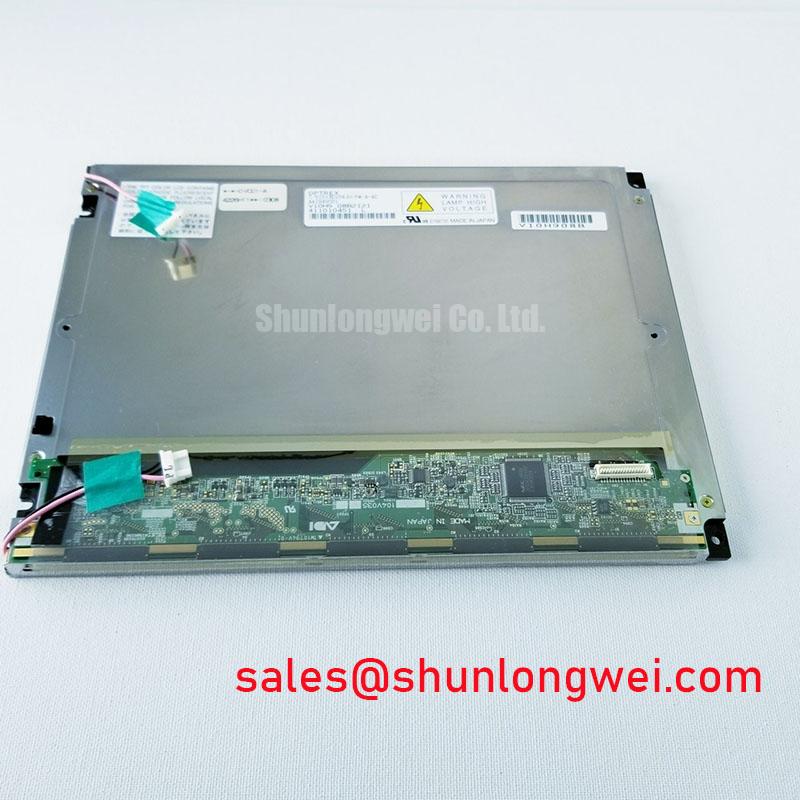
The AA104VC01 is a Mitsubishi 10.4-inch LCD display with a native 640 × 480 VGA resolution. Its official logic supply specification is 3.0 V to 3.6 V, with 3.3 V typical. The module has an official operating range of −20°C to +70°C and a storage range of −20°C to +80°C. These limits should be checked against the original equipment environmental requirements before a panel is installed into a field unit.
| Parameter | Specification | Classification |
|---|---|---|
| Display diagonal | 10.4 inches, 26 cm | Official Specification |
| Native resolution | 640 × 480 pixels, VGA | Official Specification |
| Logic supply voltage | 3.0 V to 3.6 V, 3.3 V typical | Official Specification |
| Module dimensions | 243.0 mm × 181.6 mm × 10.5 mm | Official Specification |
| Active area | 211.2 mm × 158.4 mm | Official Specification |
| Operating temperature | −20°C to +70°C | Official Specification |
| Storage temperature | −20°C to +80°C | Official Specification |
Industrial Bezel Mechanical Envelope Tolerances & Mounting Screw Torque Optimization
The first mechanical check is whether the host bezel accepts the official 243.0 mm width, 181.6 mm height, and 10.5 mm depth of the AA104VC01 without placing side load on the viewing area. A panel can appear electrically functional on the bench yet develop nonuniform dark-field appearance after it is restrained by an uneven bezel, distorted mounting plane, or compressed cable route. Confirm that the active image window clears the official 211.2 mm × 158.4 mm active area rather than using the outer module dimensions as the visible-window reference.
The supplied chassis fastening guidance of 0.25 to 0.35 N·m for M2.5 or M3 threaded studs is a Typical Starting Point, not an AA104VC01 factory torque guarantee. A cross-pattern tightening sequence helps reveal whether a mounting point is progressively drawing the panel frame out of plane. The final torque, screw length, washer arrangement, and chassis flatness remain system-dependent and should be validated on the finished assembly.
For a bezel that relies on a compliant perimeter seal, a 25% to 35% gasket deflection is a Design Consideration for closed-cell silicone foam. It is not an official panel requirement. The aim is to maintain enclosure contact without concentrating force at corners or along one edge of the display. After fastening, inspect a black raster in a dim environment, then repeat the inspection after a short period at the intended operating temperature. This compares mechanical shading with a true electrical image defect more effectively than checking only a bright desktop image.
💡 Bench Tip: Disconnect power before handling the display cable, use ESD controls, and insert the flex or harness squarely so the connector locks evenly rather than forcing one side ahead of the other.
Cold operation needs a separate distinction between the AA104VC01’s specified ambient rating and system-level response expectations. The official operating limit is −20°C; no official gray-to-gray response-time figure or heater architecture is provided here. A target ITO heater-layer power of 0.25 to 0.45 W/cm² is an Engineering Calculation for a heater layer evaluated against a −20°C ambient delta, not confirmation that this display includes such a layer. When an enclosure uses supplemental heating, the system integrator should validate warm-up behavior, local surface temperature, optical appearance, and control failure modes with the installed panel.
Micro-Twist Mechanical Stress Fracture Prevention on Glass Substrate Driver Bumps
Do not use a panel corner or the attached cable as a lifting point during incoming inspection. Hold the module by supported frame areas, place it on a clean flat fixture, and avoid twisting it while the connector is engaged. Mechanical stress can be associated with intermittent lines, color changes, or image instability, but those symptoms do not prove a particular glass-substrate or driver-bond failure mechanism. The AA104VC01 information provided does not identify the internal driver attachment method, so diagnosis should remain evidence-based.
A practical primary-color bench sequence starts with full-screen red, green, and blue patterns, followed by white and black. Observe each pattern from a normal viewing position, then use a flashlight at an oblique angle to check whether an apparent dark region changes with reflected light. A region that becomes visible only by reflected light can direct attention toward surface contamination, bezel shadowing, or optical-stack appearance. A region that follows a column, row, or repeated pixel pattern across commanded colors may justify further signal-path and panel evaluation. This sequence separates observations; it does not assign a single cause without comparison to a known-good interface path.
The AA104VC01 official data supplied here confirms the 3.3 V typical logic rail, but it does not define the video connector, pinout, TTL or LVDS signaling method, clock rate, clock-jitter allowance, data-hold requirement, or power-sequencing timing. The system integrator should verify the required supply voltage, connector orientation, signal format, and timing requirements from the original panel documentation and host controller documentation. Supplying a correct nominal logic voltage does not establish pin compatibility.
When a display shows intermittent color, frame instability, or a missing image after cable work, examine the mating connector, cable strain relief, shield termination, and return path before attributing the issue to the panel. A scope comparison against a known-good signal path can help identify signal-integrity differences. This is an Engineering Recommendation: minimize uncontrolled cable movement and preserve the original harness routing where possible, because routing changes can alter coupling to nearby switching equipment and servo wiring.
For equipment renewal planning, mechanical fit and native resolution must be checked independently. The AA084VC01 can be reviewed as a separate display option during a documented compatibility assessment, but its physical envelope, optical characteristics, connector arrangement, and electrical requirements should not be presumed equivalent to the AA104VC01.
Mitigating Gray-to-Gray Response Time Escalation during Cold-Start Machine Power-Up
At lower temperatures, liquid-crystal movement can become visibly slower, which may be noticed as delayed transitions, trailing, or temporarily uneven grayscale appearance during cold startup. This is a general display behavior and should not be converted into an unsupported AA104VC01 gray-to-gray value. The official operating range begins at −20°C; references to operation at −30°C or thermal cycling to +85°C are outside the supplied operating and storage specifications and therefore require separate system qualification rather than an assumption of suitability.
Use the cold-start test as an observation exercise. Stabilize the complete assembly at the intended ambient condition, allow the host electronics to follow their documented startup order, and present grayscale ramps together with neutral white, mid-gray, and black images. Compare the image after initial startup with the same image after thermal stabilization. If the visible behavior changes over time, record the enclosure temperature, supply behavior, controller state, and pattern used. Those records provide a more useful service baseline than a subjective report that the panel is simply slow.
Gamma-voltage generation and timing-control details are not specified for this AA104VC01 data set. It would be inaccurate to state a particular gamma architecture, timing-control-board design, or internal compensation behavior. If a grayscale fault is present, verify the original controller output and panel input conditions according to the equipment documentation. A changed grayscale response may arise from the host signal source, supply sequencing, cable integrity, environmental temperature, or the display assembly itself; controlled substitution is often more informative than a single static measurement.
Industrial equipment with nearby motor drives, contactors, or high-frequency power conversion should be assessed for conducted and radiated interference at the system level. The AA104VC01 is not represented here as independently certified for complete-system EMC compliance. As a Design Consideration, preserve grounded enclosure interfaces and intended cable shielding, then verify image stability during actual equipment switching events. Guidance on panel selection, interfaces, optical checks, and practical testing methods is available in The Ultimate Guide to Industrial TFT LCD Technology.
Where this Mitsubishi display is being evaluated for a railway passenger-information terminal or cab-signalling display, the stated temperature range and VGA format are useful starting points, but the equipment owner should confirm vibration, enclosure sealing, controller timing, viewing requirements, and applicable rail-system standards independently. The display’s published dimensions and logic supply define only part of the replacement decision.
High-Voltage Striking Potential Claims and Secondary Supply Insulation Testing
The supplied AA104VC01 specifications do not identify the backlight technology, backlight input connector, inverter requirement, LED driver requirement, cold-strike voltage, dimming method, PWM frequency, acoustic-noise behavior, insulation rating, or backlight lifetime. Claims of 1500 to 1650 Vrms striking potential, 1000:1 PWM dimming, or a quantified operating-life figure must therefore not be assigned to this model without the relevant official documentation for the exact panel and its original backlight assembly.
For a field replacement, identify the panel-side and host-side connectors before applying power. Read the original equipment service information to determine whether a separate illumination supply exists and whether that supply remains inside the monitor assembly or travels through the panel harness. The system integrator should verify every connector pin function from original documentation rather than inferring it from connector shape, cable count, or an apparently similar Mitsubishi panel.
When secondary insulation testing is required by the equipment maintenance procedure, test the complete, correctly identified supply assembly under the applicable service standard. Do not select a hipot level from generic CCFL or LED examples and apply it to an undocumented AA104VC01 interface. Such tests can damage connected assemblies if the test configuration, disconnected loads, grounding arrangement, and allowed procedure are not known. The responsible system engineer should define the test method and acceptance criteria.
If the host platform requires a separate display solution for a different subsystem, the TCG121WXLPAPNN-AN20-S is available for objective review as another industrial display product. Its specifications, interface, mounting arrangement, and illumination requirements must be checked independently; it should not be treated as an electrically interchangeable AA104VC01 assembly.
During the final powered inspection, use a low, medium, and high image level where the original equipment permits brightness control, then observe the panel for repeatable luminance variation, image flicker, unexpected noise from external power assemblies, or behavior that changes when cable routing is disturbed. Record only repeatable findings and compare them with the original system documentation before replacing the panel, cable, controller, or auxiliary power hardware.